Kelvinator Gas Continuous Flow hot water system clearances 9
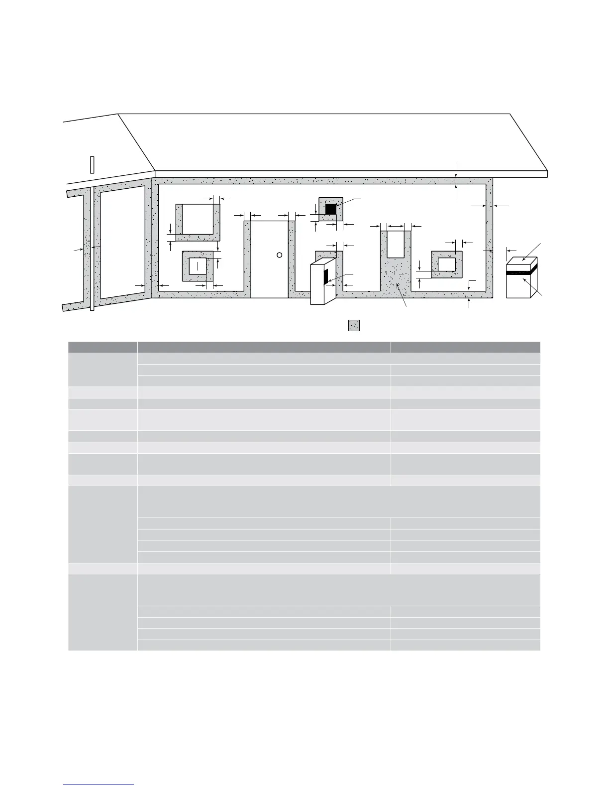
Clearances for outdoor heater locations –
AS5601
f
c
k
k
j
j j
h
h
h
T
T
g
e e
a
d
b
c
g
T
d
see note 2
T – Flue terminal
I – Mechanical air inlet
M – Gas meter
P – Electricity meter
or fuse box
Shading indicates prohibited
areas for flue terminals
see note 3
P
n
openable
window
Reference Item Minimum clearances (mm)
a Below eaves, balconies and other projections:
• appliances up to 50MJ/h input 200
• appliances over 50MJ/h input 300
b From the ground above a balcony surface* 300
c From a return wall or external corner* 300
d
From a gas meter (M) (see 4.7.11 for vent terminal location
of regulator)
1000
e From an electricity meter or fuse box (P) 500
f From a drain or soil pipe 75
g
Horizontally from any building structure* or obstruction facing
a terminal
500
h From any other ue terminal, cowl or combustion air intake 300
j
Horizontally from an openable window, door, non-mechanical
air inlet or any other opening into a building with the exception
of sub-oor ventilation
• Appliances up to 150 MJ/h input 300
• Appliances over 150 MJ/h input up to 200 MJ/h input 500
• Appliances over 200 MJ/h input 1500
• All fan-assisted ue appliances in the direction of discharge 1500
k From a mechanical air inlet, including a spa blower 1000
n
Vertically below an openable window, non-mechanical air
outlet or any other opening into a building with the exception
of sub-oor ventilation
• Space heaters up to 50 MJ/h input 150
• Other appliances up to 150 MJ/h input 500
• Appliances over 50 MJ/h input up to 150 MJ/h input 1500
• Appliances over 150 MJ/h input 1500
*unless appliance is certified for closer installation.
NOTES:
1. All distances are measured to the nearest part of the
terminal.
2. Prohibited area below electricity meter or fuse box
extends to ground level.
3. See clause 15.3.6.6 for restrictions on a ue terminal
under a covered area.
4. See Appendix J, gures J2(a) and J3(a) for clearances
required from a flue terminal to an LP gas cylinder. A flue
terminal is considered to be a source of ignition.
5. For appliances not addressed above, acceptance should
be obtained from the technical regulator.
Exemption from prescribed statuatory requirements
referred to above has been granted to allow multiple series
of the water heaters to be positioned side by side.
This diagram and reference table has been taken from the AS/NZS 5601 standard regarding gas installations. Any references on this page to
clauses or appendix figures are referring directly to this standard.
 Loading...