1
2
3
4
5
6
7
8
9
H
L
1
3
2
1 2 3
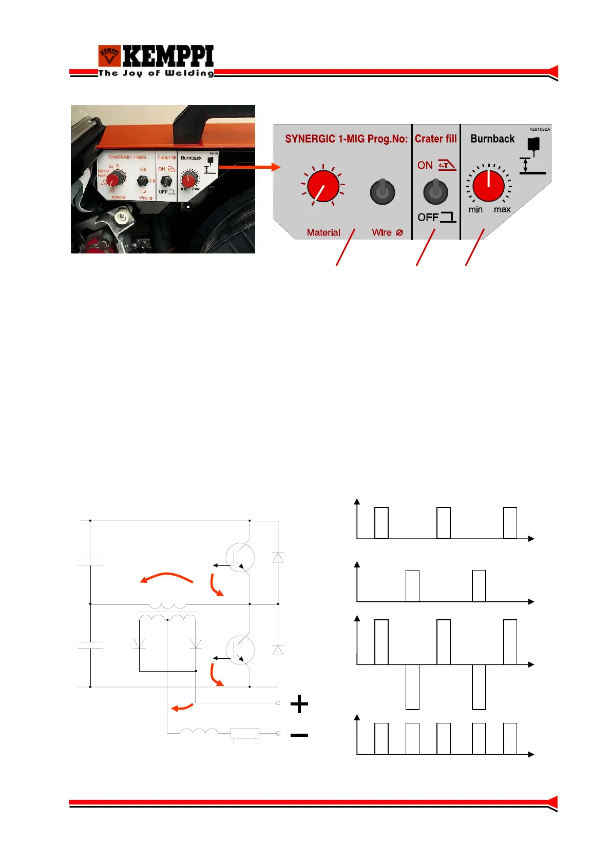
1 Synergic program selection
2 Crater fill on/off
3 Post current adjustment 40 ms…760 ms
Operation principle
Kempomig- power sources power stage is a traditional half-bridge, where the DC-link´s voltage is
halved by load capacitors C2 and C3. IGBT transistors work as power switches.
When both IGBTs are non-conductive, no power is transferred. When the upper IGBT (V2) is
conductive, there is positive voltage in the main transformer´s (T1) primary, and when the lower
IGBT (V3) is conductive there is negative voltage in the main transformer´s (T1) primary.
Power is adjusted by changing the IGBT timings (PWM). Main transformer T1 secondary
voltages are rectified with a full-waverectifier.
U
G2
t
U
G3
t
U
1
t
U
2
t
C2
C3
V2
V3
T1
U
1
U
2
U
G2
U
G3
approx. + 570 V
5
 Loading...