TTC 130, TTC 130F, TTC 160, TTC 160S, TTC 220, TTC 200W, TTC 250W, – 7
TTC 250WS/0109
© COPYRIGHT KEMPPI OY
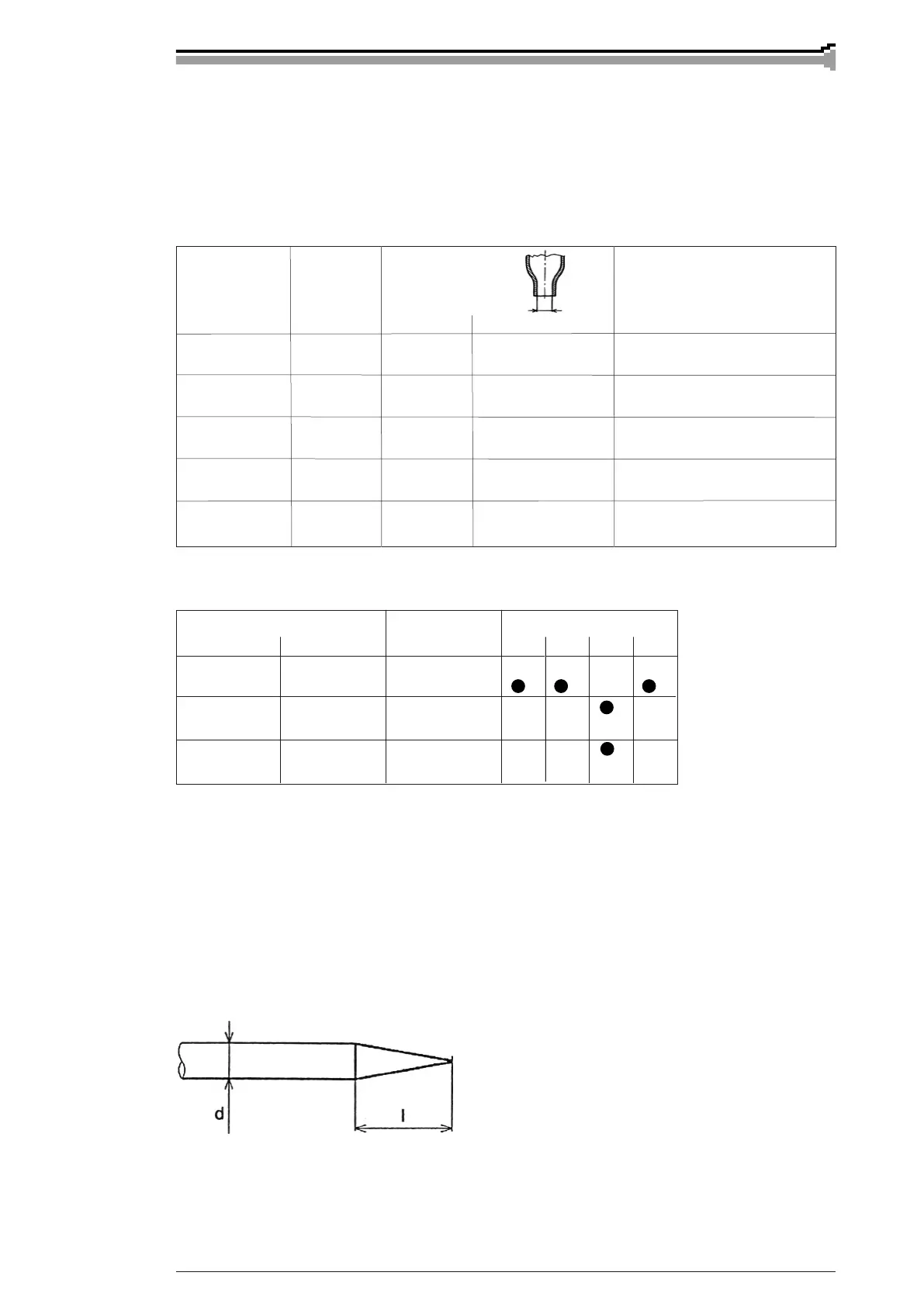
I = 1...5 x d
2.4. CHOICE OF ELECTRODE SIZE AND FLOW AMOUNT
OF SHIELDING GAS
Electrode size and shielding gas ow are dened by welding current level. The most usual
shielding gas for TIG welding is argon.
The table below is given only as a guide.
Welding current Electrode Gas nozzle Gas ow rate
DC-
(AC)
A Ø mm Number Ø mm l/min
5…80 1,0 4/5 6,5/8,0 5…6
(5…50)
70…150 1,6 4/5/6 6,5/8,0/9,5 6…7
(30…100)
130…250 2,4 6/7 9,5/11,0 7…8
(80…150)
220…350 3,2 7/8/10 11,0/12,5/16,0 8…10
(120…210)
330…500 4,0 10/11/12 16,0/17,5/19,0 10…12
(180…280)
Electrode Welding current Base material
Type Symbol colour Fe Ss Al Ti
WC20 grey AC
DC-
WZ8 white AC
DC-
W green AC
DC-
2.4.1. Electrode choice according to base material to be welded
Delivery length of electrodes is 175 mm.
Data in table are given only as a guide.
2.5. SHARPENING OF ELECTRODE
2.5.1. D.C. welding
In D.C. welding the tip of electrode is sharpened into cone shape in order to get a steady arc and
to concentrate heat energy on welding point. Size of sharpening angle has an effect on width of
welding run and depth of penetration. Ratio of sharpening length to electrode diameter:
 Loading...