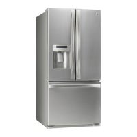
Do you have a question about the Kenmore 795.7105 series and is the answer not in the manual?
Introduces the FPB 1202/1502 panel PC series and its design for industrial environments.
Details general specifications including construction, disk drive housing, and environmental ratings.
Outlines the key features of the FPB 1202 model, including its LCD, chassis, CPU, and ports.
Provides in-depth technical specifications for the FPB 1202 model, covering hardware and interfaces.
Shows physical dimensions for the FPB 1202 model, including cutout suggestions for panel mounting.
Describes the procedure for mounting the display panel onto a control panel.
Step-by-step instructions for installing a 3.5-inch Hard Disk Drive into the unit.
Instructions for installing slim CD-ROM drives, FDDs, and 2.5-inch HDDs.
Introduces the FBP CPU card, its integrated design, and features like Ethernet and memory support.
Lists the key features of the CPU card, including CPU support, DiskOnChip, and controller capabilities.
Details the standard SBC functions, interfaces, memory, and I/O capabilities of the CPU card.
Provides a visual diagram showing the arrangement of components on the CPU card.
Presents detailed dimensional measurements of the CPU card for integration purposes.
Introduces board jumpers and connectors, listing their functions for system configuration.
Explains how to configure the board's functionality by setting jumpers.
Provides instructions for installing or upgrading the CPU on the FC-370 socket.
Guides on installing SDRAM modules (DIMMs) into the CPU card's memory sockets.
Details how to configure the LCD clock signal and driving voltage using jumper J1.
Explains how to set the COM2 serial port mode (RS-232, RS-422, RS-485) via jumpers.
Details the pin assignments and signal/color coding for the PWR1 power connectors.
Describes the CRT and flat panel display connectors (CN8, CN2) and their functions.
Explains the keyboard and PS/2 mouse connectors and their configuration options.
Describes the serial ports (CN11, CN5) and their pinout for connecting serial devices.
Explains the IDE hard drive connector CN10 for attaching IDE hard disk drives.
Details the floppy drive connector CN12 for connecting floppy disk drives.
Describes the DiskOnChip socket U10 for solid-state flash disk installation.
Explains how to enter the Award BIOS Setup utility during system startup.
Lists the function and navigation keys used within the BIOS Setup utility.
Overviews the main menu options available for configuring the system via BIOS.
Details the configuration options within the Standard CMOS Setup menu.
Covers configuration options related to BIOS features for system performance.
Explains chipset-specific configuration options for system resources and performance.
Details settings for managing system power consumption and saving features.
Guides on configuring Plug-and-Play and PCI devices for resource allocation.
Explains how to set supervisor and user passwords for BIOS access and security.
Describes the procedure for saving configuration changes and exiting the BIOS setup.
Describes the operation and installation of display drivers supplied on the CD-ROM.
Provides tips for configuring display hardware for optimal driver performance.
Guides on installing display drivers for Windows 95 operating system.
Guides on installing display drivers for Windows NT 3.51 operating system.
Guides on installing display drivers for Windows NT 4.0 operating system.
Describes how to configure the onboard Ethernet interface using the Award BIOS Setup.
Explains how to program the system's watchdog timer for reliability in industrial environments.
Provides specific steps and register values for setting the watchdog timer's time-out.
Demonstrates programming the watchdog timer using assembly language code.
Provides guidance on troubleshooting and debugging product issues with technical support.
Outlines the warranty terms, conditions, and procedures for returning products.
| Brand | Kenmore |
|---|---|
| Model | 795.7105 series |
| Category | Refrigerator |
| Language | English |