4
YourKenmorepowerunitdoesnotrequiretheassemblyofamufer.
YourCVShasthemuferinstalledinternally.Youmayhoweverdesireto
exhausttheairoutside.Inthiscaseyouwillneedtoattachtheexhaust
adapter. This will convert the size of the exhaust to the diameter of the
central vacuum pipe.
Refertopage15-Image5
• Placethepowerunitinordertomaketheexhaustpipeasshortas
possible.Exhaustsshouldbelimitedtonolongerthan16.5ft(5m).
• Keepinmindthatyoumayneedspaceonthesidesofyour
central unit to be able to access the dirt receptacle.
Refertopage15-Image6
• Alignthepowerunitintakettingtothemaintrunklineprojectingfromthe
wall.
DO NOT GLUE. Attach the exhaust pipe to the motor exhaust if
exhaustingoutdoors.Makesuretheexhaustpipeisasshortaspossible.
NOTE:Mountcentralpowerunitatleast12in(30cm)fromtheceiling
andanyadjacentwall,atleast27.5in(70cm)fromtheoorandwithin6ft
(1.8m)ofanelectricaloutlet.Reviewanylocalregulationsthatmayapply.
Refertopage15-Image2
WARNING
Donotblockthehoodventilationopeningsonthetopofthecentral
power unit. Lack of ventilation will cause the motor to overheat.
WARNING
Donotlocatethecentralpowerunitinahightemperatureareawhereit
is inaccessible for example, an attic or crawl space.
For the ultimate in air control you have the 650 series. The 650 series
features a true HEPA filter and may be included with your choice of
power unit or can be purchased from an authorized dealer/distributor.
Simply attach the true HEPA filter as shown.
Refertopage15-Image7
SYSTEM TEST
Be certain to comply with local electrical codes and regulations. Plug
the unit into a regular electrical outlet. You are now ready to check the
installation of the unit:
• Besurethelterisproperlyinstalledinthepowerunit.
• Besurethedirtreceptacleisproperlysecuredtothepowerunit.
• Plugthehoseintoeachinletvalvetobesuretheelectrical
contacts operate properly.
• Checkeachinletvalveforairleaks.
• Checkeachpipeconnectionforairleaks.
Refertopage15-Image8
HOW TO USE CENTRAL VACUUM SYSTEM
Your central vacuum system is controlled by a switch on your hose.
Simply insert the hose into the valve and turn the switch to the on position.
This will start the power unit and the flow of air.
When you are finished, turn the switch on the hose to the off position
and remove the hose from the inlet valve. When unplugging the hose,
hold the inlet cover open for a few seconds to allow suction to decrease
thus, protecting the inlet valve seal.
Refertopage15-Image8
LED INDICATIONS - OPTIONAL DEPENDING ON MODEL
Youmachinemaybeequippedwithsomeoralloftheindicatorslistedbelow.
Refertopage15-Image9
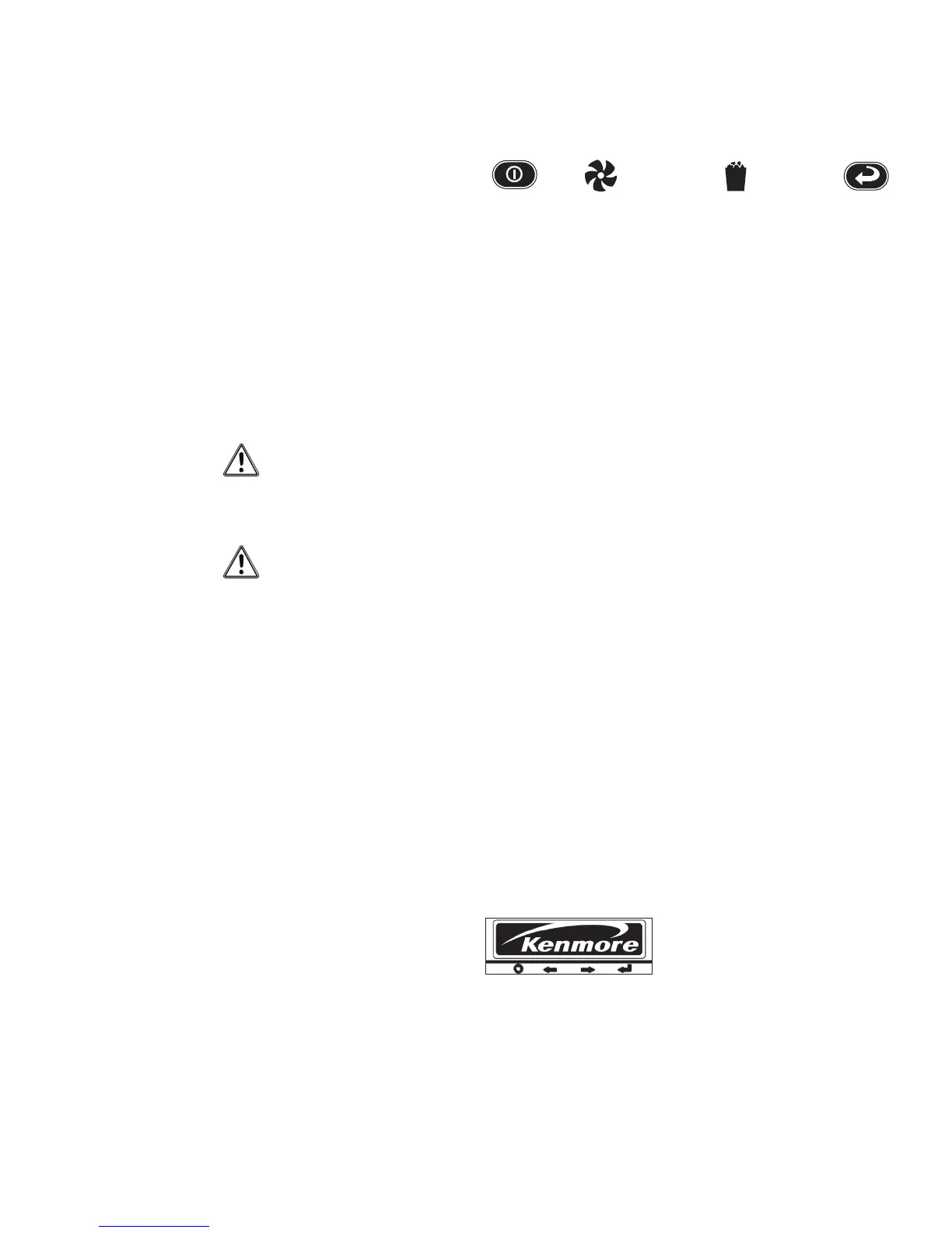
On/Off MotorFault DirtReceptacleFull Reset
YourpowerunitisequippedwithamulticolorLEDpanel.ThisLED
panelwillprovideyouwithnecessaryinformationonyourpowerunit’s
performance, maintenance and diagnostics. Below are descriptions
of the different messages the power unit will provide.
NORMAL OPERATION
When the power unit is OFF and considered to be in standby mode the
LEDbuttonwillbeRED.
WhenthepowerunitisONandinusetheLEDwillbeGREEN.When
the motor fault light is ON see further description below. When the dirt
receptacle light is ON, empty dirt receptacle and press the RESET
button,andholdfor10seconds.
WhenyouLCDpowerunitisinstandbymodethefourwhitelightsonyour
LCDunitwilllightupinsequenceandalternatemovingfromlefttoright
then reversing right to left. This pattern will repeat continuously and is an
indication that your power unit is ready for use and functioning properly.
MOTOR FAULT
Inthecaseofablownfuseordisconnectedmotorwireandthepower
unitisnotfunctioningtheON/OFFbuttonwillbeconstantlyGREENInthe
caseofanovercurrentshutdown,theON/OFFbuttonwillbeashingRED,
theGREENlightwillonandoffrapidlyandtheMOTORFAULTlightwillbe
AMBERandturnonandoffrapidly.Thisfaultwillresetautomaticallyin
15secondsifthelowvoltconnectionisOFFatthehose.
Inthecaseofacontinuedovercurrentandthelowvoltconnectionis
ONandthehosetheON/OFFbuttonwillconstantlybeRED,theGREEN
lightwillashslowlyandtheMOTORFAULTwillslowlyashAMBER.
Intheunlikelyeventofabadfrequencyreceivedbythepowerunitthe
powerunitwillnotstartandtheON/OFFbuttonwillremainconstantlyRED.
InthecaseofahighlinevoltagereceivedbythepowerunittheON/OFF
buttonwillalternatebetweenREDandGREENthreetimes-pausebriey
–alternatebetweenREDandGREENthreetimes–longpause-andthen
repeat. This will continue until the line voltage returns to the correct level.
LCD SCREEN - OPTIONAL
Refertopage15-Image8
650 SERIES
InthemainscreenoftheLCD,theKenmorelogowillappear.Thislogo
may scroll from side to side to avoid the image ingraining itself onto the
LCDDisplay.Youwillseethelogowhenthepowerunitisnotinuse.
The button that best lines up with the Power symbol on the screen can
be used to activate the unit. Press this button to toggle the unit on/off.
The unit may also be activated from any installed inlet.
 Loading...