13. If all of data is set and no other change needed, press “FUNC” Button. “- -” appears on the Digital
Display, and the opener enters standby mode.
Indicate Illustration on the Digital Display When Gate Opener is
Running
The RIGHT image on Digital Display symbolizes motor of ARM 1 when the gate opener is running. The
LEFT image on Digital Display symbolizes motor of ARM 2.
When the motor is run to gate -open direction or gate -close direction, the image on Digital Display
indicates “n” or “u” respectively.
When the motor is not running, the Digital Display indicates “- -”.
When Gate Opener 2 is set as Master gate (i.e. when “10” indicated at P2 set mode in the Control Board),
the Digital Display flashes “-n” before the gate completely opens and closes.
How to Operate
The user may operate the opener once all adjustment setting is finished.
With the gate in its closed position, press and release the remote control, the gate will move to the
programmed opening position and stop.
With the gate in its opened position, press and release the remote control, the gate will move to the
programmed closing position and stop.
While the gate is moving, press and release the remote control, the gate will stop moving immediately. The
next command from the remote will reverse the gate direction and the gate will stop at its programmed
opening/closing position.
The gate will stop in case of obstruction during opening. The command from the remote control will reverse
the gate direction and the gate will stop at its programmed closing position.
The gate will reverse in case of obstruction or stall force during closing, and it will move to the programmed
opening position.
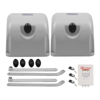
Installation for Push-to-Open Gates
Ensure the gate does not open into public areas.
The connection by “Push to Open” is different from the connection by “Pull to Open”.
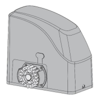
Connection of arm 1(Installed in the left side )
The MOTOR+ terminal of the arm should be connected to the +MOTOR1 terminal of the control board. The
MOTOR- terminal should be connected to the MOTOR1- terminal of the control board. The DN terminal
should be connected to the ULT1 terminal of the control board. The COM terminal should be connected to
the COM terminal of the control board. The UP terminal should be connected to the DLT1 terminal of the
control board.