Do you have a question about the Kenwood 4042A - KGC Equalizer / Crossover and is the answer not in the manual?
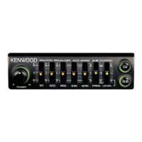
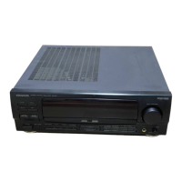
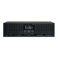
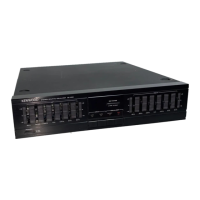
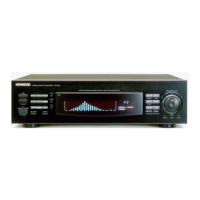
Identifies and describes the function of front panel knobs and displays.
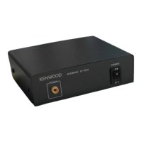
Details the included cables and connection ports for the unit.
Illustrates the overall signal flow through EQ, filters, amplifiers, and output stages.
Shows the power supply section and control logic for the equalizer.
Layout showing component placement on the main circuit board.
Layout showing copper traces on the main circuit board.
Layout showing component placement on the EQ ON/OFF circuit board.
Layout showing copper traces on the EQ ON/OFF circuit board.
Details the input signal processing and equalizer stages, including ICs and filters.
Covers audio amplification, low/high pass filters, and output signal routing.
Illustrates the power supply section, switching transistors, and control functions.
Visual representation of how the unit's components are assembled.
Highlights the placement of major internal parts like PCBs and switches.
Details external cables, connectors, and mounting hardware shown in the exploded view.
Lists electric unit capacitors (C series) and connectors (CN series).
Details transistors (Q series), integrated circuits (IC series), and lamps/LEDs.
Catalog of resistors, including chip resistors and leaded types, with their values.
Lists variable resistors (VR) and switches (SW) used in the unit.
Details specific connectors and sockets for unit assembly.
Lists diodes (D series) and transistors (Q series) with their part numbers and types.
Specifies audio parameters like input impedance, S/N ratio, and equalizer frequency response.
Outlines operating voltage, current consumption, dimensions, and weight.
| Type | Equalizer / Crossover |
|---|---|
| Brand | Kenwood |
| Model | 4042A - KGC |
| Category | Recording Equipment |
| Channels | 2 |
| Equalization | Yes |
| Equalization Range | ±12dB |
| Subwoofer Output | Yes |
| Signal to Noise Ratio | 95dB |
| Power Requirement | 12V DC |