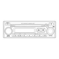
Do you have a question about the Kenwood CKDC-MP575 and is the answer not in the manual?
Details the terminals and functions of the system microcomputer.
Describes power supply, mecha control, and µ-COM operations.
Instructions for entering, releasing, and operating in test mode.
Explains operations performed with specific keys in test mode.
Procedures for security, forced power-on, and clearing codes.
Confirmation modes for DC offset, memory clear, and channel switching.
Adjustment points and settings for AM and FM tuning.
| FM frequency range | 87.9MHz~107.9MHz |
|---|---|
| AM frequency range | 530kHz~1700kHz |
| Stereo separation | 40dB (1kHz) |
| CD spindle speed | 1000rpm~400rpm |
|---|---|
| CD total harmonic distortion | 0.01% (1kHz) |
| CD S/N ratio | 105dB (1kHz) |
| Maximum power | 50W x 4 |
|---|---|
| Full bandwidth power | 22W x 4 |
| Preout level / load | 2000mV/10kΩ (CD/CD-CH) |
| Bass | 100Hz±10dB |
|---|---|
| Middle | 1kHz±10dB |
| Treble | 10kHz±10dB |
| Operating voltage | 14.4V |
|---|---|
| Current consumption | 10A |
| Weight | 1.40kg (3.1 lbs) |








 Loading...