Do you have a question about the Kenwood KA-5750 and is the answer not in the manual?
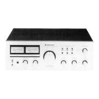
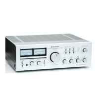
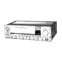
Overview of front panel components including meters, knobs, and selector switches.
Illustration and labeling of all input/output jacks and speaker terminals on the rear.
Identification of key internal assemblies like the power transformer, power supply, and circuit boards.
Locating internal switches, relays, lamps, and potentiometers.
Procedure for removing front panel components, including knobs, and accessing internal parts.
Guidance on accessing specific internal components and separating bases during disassembly.
Schematic representation of signal flow and levels within the amplifier.
Explanation of key circuit types used, including differential amplifier and protection circuits.
List of miscellaneous parts, capacitors, and resistors.
Catalog of transistors, diodes, FETs, and other semiconductor devices.
Steps to calibrate the power meter to accurately display output levels.
Procedure for measuring and confirming bias current within specified limits.
Diagram showing the placement of components on the main audio PC board.
Table of absolute maximum ratings for transistors and FETs.
Detailed circuit diagram illustrating the amplifier's internal wiring and component layout.
Guide to alternative semiconductor parts for common components.
Specifications detailing the amplifier's power output capabilities and distortion levels.
Key general specifications such as dimensions, weight, and power consumption.
| Type | Stereo Integrated Amplifier |
|---|---|
| Damping Factor | 50 |
| Input Sensitivity | 2.5mV (MM), 150mV (line) |
| Signal-to-Noise Ratio | 76dB (MM) |
| Output | Speaker terminals, headphone jack |
| Speaker Load Impedance | 4 to 16 ohms |