EasyManua.ls Logo

Kenwood KAC-526 User Manual

Kenwood KAC-526
16 pages
To Next Page IconTo Next Page
Page #1 background imageLoading...
Page #1 background image
POWER
AMPLIFIER
KAC-
INSTRUCTION
MANUAL
KENWOOD
CORPORATION
©B64-0781-00
(K)(MC)
Take
the
time
to
read
through
this
instruction
manual.
Familiarity
with
installation
and
operation
procedures
will
help
you
obtain
the
best
performance
from
your
new
power
amplifier.
For
your
records
Record
the
serial
number,
found
on
the
back
of
the
unit,
in
the
spaces.designated
on
the
warranty
card,
and
in
the
space
provided
below.
Refer
to
.the
model
and
serial
numbers
whenever
you
call
upon
your
KENWOOD
dealer
for
information
or
service
on
the
product.
Model
KAC-526
SeriaJ_number_;_
Safety
preCMutiom
I
awabwingI
Take
the
following
precautions
to
prevent
fire
and
avoid
personal
injury:
When
extending
the
battery
cable,
or
ground
cable,
use
3mm*
(AWG12)
or
larger
automotive
grade
cable
to
avoid
cable
deterioration
or
damage
to
the
covering.
Check
that
no
metal
objects
(coins,
tools,
etc.)
are
left
inside
the
unit
to
avoid
short
circuits.
If
you
smell
or
see
smoke,
turn
the
power
off
immediately
and
consult
your
Kenwood
dealer.
Do
not
touch
the
unit
during
use
because
the
surface
of
tfie
unit
becomes
hot
and
may
cause
burns
if
touched.
I
ACAUTiOin
Take
the
following
precautions
to
keep
the
unit
in
proper
working
order.
Be
sure
the
unit
is
connected
to
a
12V
DC
power
supply
with
a
negative
ground
connection.
Do
not
open
the
top
or
bottom
cover.
Do
not
install
the
unit
in
places
it
is
exposed
to
direct
sunlight,
high
heat
or
humidity,
water
may
splash
over
it,
or
dust
exists.
f
NOTE
I
If
you
have
difficulty
in
installing
this
unit
in
your
vehicle,
contact
your
Kenwood
dealer.
Cleaning
the
unit
If
the
surface
is
dirty,
wipe
it
clean
with
a
silicon
cloth
or
soft
dry
cloth
with
the
power
off.
I
ACAUTiOin
Do
not
use
hard
cloths
or
paint
thinner,
alcohol,
or
other
volatile
solvents.
These
may
damage
external
surfaces
or
remove
indicator
characters.
FCC
WARNING
This
equipment
may
generate
or
use
radio
frequency
energy.
Changes
or
modifications
to
this
equipment
may
cause
harmful
interference
unless
the
modifications
are
expressly
approved
in
the
instruction
manual.
The
user
could
lose
the
authority
to
operate
this
equipment
if
an
unauthorized
change
or
modification
is
made.
Accessories
Part
name
External
View
Number
of
Items
Self-tapping
screws
(04
16mm)
4
Terminal
cover
(Power
terminal
1
Question and Answer IconNeed help?

Do you have a question about the Kenwood KAC-526 and is the answer not in the manual?

Kenwood KAC-526 Specifications

General IconGeneral
BrandKenwood
ModelKAC-526
CategoryCar Amplifier
LanguageEnglish

Summary

Safety Precautions

General Safety Warnings

Precautions to prevent fire and avoid personal injury during installation and operation.

Operational Safety Precautions

Precautions to keep the unit in proper working order and avoid damage.

Cleaning the Unit

Instructions for cleaning the unit's surface using appropriate materials.

Cleaning Cautions

Warnings against using harsh chemicals or solvents that can damage the unit's finish.

FCC Warning

Information regarding potential radio frequency energy and user modifications.

Accessories Included

Controls Overview

RCA Cable Ground Lead Terminal

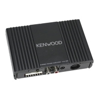
Terminal for connecting the ground lead of an RCA cable.

Operation Switch

Switch to select amplification method: STEREO or MONO (Lch).

Input Sensitivity Control

Control to set sensitivity based on pre-output level or max power output.

Line In Terminal

Input terminal for audio signals via RCA cables.

Speaker Level Input Terminal

Input terminal for speaker level signals.

Fuse (15A)

Protective fuse for the unit, rated at 15 Amperes.

Battery Terminal

Connection point for the positive (+) power supply from the battery.

Ground Terminal

Connection point for the negative (-) power supply ground.

Power Control (Remote) Terminal

Terminal for the remote turn-on signal from the source unit.

Speaker Output Terminals

Terminals for connecting speakers to the amplifier output.

Protection Function

Power Indicator

Indicator light that shows when the unit is powered on.

Protection Activation Conditions

Situations triggering the protection function, such as short circuits or overheating.

Installation Procedure

Installation Fuse Cautions

Advice on checking cables for shorts and replacing blown fuses.

Installation Location Cautions

Warning against installing the unit under carpets due to heat build-up.

Heat Dissipation Installation

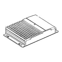
Guidance on installing the unit in a location that allows for efficient heat dissipation.

Final Installation Checks

Ensuring proper operation of vehicle electrical equipment after installation.

Tri-mode Operation

Principle of Tri-mode

Explanation of frequency band division using coils and capacitors in tri-mode.

Coil and Capacitor Calculation

Formulas and examples for calculating required coil and capacitor values.

Tri-mode System Example

Diagram illustrating the tri-mode configuration with speakers and subwoofer.

Bridged Connection Caution

Warning regarding minimum speaker impedance (4 ohms) for bridged connections.

System Connection

RCA Cable Ground Lead Terminal

Connecting the ground lead of an RCA cable to the specified terminal.

Power Terminal Connections

Connecting battery and ground cables through the terminal cover.

Speaker Output Terminals

Connecting speaker output cables to the appropriate terminals.

Noise Filter Recommendation

Suggestion to use a line noise filter for buzzing noise during engine operation.

Wiring Fire Prevention

Warning to install a fusible link or breaker near the battery for fire prevention.

Connection with Genuine-Accessory Car Stereo

Speaker Level Input Terminal

Connecting the speaker level input cable to the designated terminal.

Accessory Car Stereo Power Limit

Limitation of genuine-accessory car stereo power output to 25W.

Input Connection Conflict Caution

Warning against simultaneous RCA and speaker input connections.

Power Control Lead Connection

Connecting the power control lead to the ignition key switch (ACC line).

System Examples

Demonstrations of various audio system configurations using the unit.

Troubleshooting Guide

No Sound Issue

Troubleshooting steps for when no sound or sound from one side is present.

Output Level Adjustment

Guidance for resolving issues with output level being too small or too large.

Sound Quality Issues

Troubleshooting distorted sound due to incorrect connections or pinched cables.

Specifications

Audio Section Specifications

Detailed technical specifications for audio output and response.

General Specifications

Technical details including operating voltage, current consumption, and weight.

Related product manuals