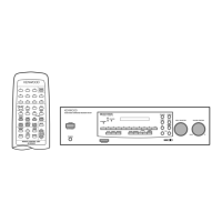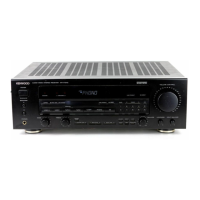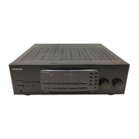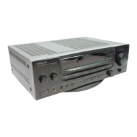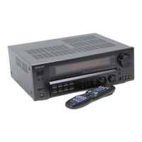
Do you have a question about the Kenwood KR-6600 and is the answer not in the manual?
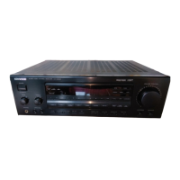
| Power Output | 60 watts per channel into 8Ω (stereo) |
|---|---|
| Speaker Load Impedance | 4Ω to 16Ω |
| Tuning Range | FM, MW |
| Frequency Response | 20Hz to 20kHz |
| Input Sensitivity | 2.5mV (MM), 150mV (line) |
| Signal to Noise Ratio | 70dB (MM), 90dB (line) |
| Frequency Response Extended | 10Hz to 50kHz |
Instructions for disassembling the preamp section.
Steps to remove the power amp unit.
Procedure for stringing the dial cord.
Overall system block diagram.
Description of the FM Radio Frequency circuit.
Description of the Intermediate Frequency circuit.
Explanation of the FM muting detection procedure.
Details on the FM Multiplex circuit.
Description of the AM tuner circuit.
Explanation of protection circuits.
Test procedures for the FM tuner section.
Test procedures for the AM tuner section.
Test procedures for the audio circuits.
Parts list for the tuner assembly.
Parts list for Power Supply Unit (A).
Parts list for the tuner unit.
Parts list for Power Supply Unit (B).
Parts list for Power Supply Unit (C).
Parts list for the power amplifier unit.
Parts list for the preamp unit.
Parts list for the microphone amplifier.
Parts list for the control amplifier.
Component breakdown for the sub-muting circuit.
PCB layout for the sub-muting circuit.
PCB layout for Power Supply Unit (A).
PCB layout for Power Supply Unit (B).
PCB layout for Power Supply Unit (C).
PCB layout for the preamp unit.
PCB layout for the tuner unit.
PCB layout for the power amplifier unit.
PCB layout for the control amplifier.
PCB layout for the microphone amplifier.
Technical specs for the FM tuner section.
Technical specs for the AM tuner section.
Specs for input sensitivity, frequency response, etc.
Specs for output power and distortion.
Overall power, dimensions, and weight.
Schematic for tuner, power amp, and sub-muting units.