EasyManua.ls Logo

Kenwood NX-740H User Manual

Kenwood NX-740H
54 pages
To Next Page IconTo Next Page
Page #1 background imageLoading...
Page #1 background image
SERVICE MANUAL
COPYRIGHT © 2014 JVC KENWOOD Corporation
No.RA010<Rev.001>
2014/5
B5B-7126-00
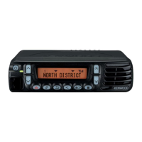
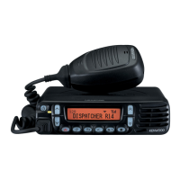
VHF DIGITAL TRANSCEIVER
RA010<Rev.001>20145SERVICE MANUALB5B-7126-00
NX-740H, NX-740H(V), NX-740
COPYRIGHT © 2014 JVC KENWOOD Corporation
Note :
Lead free solder used in the board (material : Sn, Ag, In, Bi, melting point : 227 Centigrade)
TABLE OF CONTENTS
1 PRECAUTION. . . . . . . . . . . . . . . . . . . . . . . . . . . . . . . . . . . . . . . . . . . . . . . . . . . . . . . . . . . . . . . . . . . . . . . . . 1-4
2 SPECIFIC SERVICE INSTRUCTIONS . . . . . . . . . . . . . . . . . . . . . . . . . . . . . . . . . . . . . . . . . . . . . . . . . . . . . . 1-4
3 DISASSEMBLY . . . . . . . . . . . . . . . . . . . . . . . . . . . . . . . . . . . . . . . . . . . . . . . . . . . . . . . . . . . . . . . . . . . . . . 1-21
4 ADJUSTMENT . . . . . . . . . . . . . . . . . . . . . . . . . . . . . . . . . . . . . . . . . . . . . . . . . . . . . . . . . . . . . . . . . . . . . . . 1-23
5 TROUBLESHOOTING . . . . . . . . . . . . . . . . . . . . . . . . . . . . . . . . . . . . . . . . . . . . . . . . . . . . . . . . . . . . . . . . . 1-29
ACC.
T
his product complies with the RoHS directive for the European market.
This product uses Lead Free solder.
Question and Answer IconNeed help?

Do you have a question about the Kenwood NX-740H and is the answer not in the manual?

Kenwood NX-740H Specifications

General IconGeneral
BrandKenwood
ModelNX-740H
CategoryTransceiver
LanguageEnglish

Summary

Specific Service Instructions

System Setup and Realignment

Covers transceiver setup, modes, and realignment procedures.

PC Mode and Clone Mode Operations

Details PC programming, interface cables, software, and clone mode data transfer.

Installation and Horn Alert Setup

Covers connecting optional cables and setting up the Horn alert feature.

Ignition Sense and External Speaker

Explains installation of ignition sense cable and connection of external speakers.

Circuit Description

Frequency and Receiver System Overview

Explains frequency configuration and the receiver system's block diagram.

AF Signal, Squelch, and Transmitter Overview

Describes AF signal paths, squelch circuit, and the transmitter system outline.

APC, PLL, and VCO Circuitry

Details the APC circuit, PLL frequency synthesizer, and VCO operation.

Control Circuitry and Display

Explains the control circuit's functions for ICs, memory, and display.

Key Matrix and Signaling Circuits

Covers key matrix operation and signaling encoding/decoding.
Disassembly Procedures

Adjustment Procedures

Troubleshooting

Schematic Diagrams

Level Diagrams

Block Diagrams

Parts List Information

Related product manuals