Do you have a question about the Kenwood NX-800 and is the answer not in the manual?
Steps to plan the installation of the radio and antenna in a vehicle.
Precautions for personal safety during operation and servicing.
Information on servicing and referring to diagrams and procedures in the manual.
Steps before installing the radio, including unpacking and checks.
Details on entering and using the panel test mode for diagnostics.
Information on entering and using the panel tuning mode for adjustments.
Steps and procedures for connecting the transceiver to a PC for programming.
Installation of the ignition sense cable for power control via car ignition.
Installation of the Horn Alert/P.A. Relay Unit for expanded audio functions.
Installation of the control head remote kit for remote operation.
Installation of the Voice Guide & Storage Unit for audio prompts and storage.
Connection procedure for the KES-3 external speaker.
Installation and setup for KES-5 or KES-6 external speakers with KAP-2.
Installing the GPS receiver unit, including connection and placement.
Installing the GPS receiver and VGS-1 unit simultaneously.
Important precautions to follow before and during the disassembly process.
Precautions for reassembling the TX-RX PCB unit after repair.
Description of the power supply circuit, including voltage regulation and distribution.
Steps to check power supply voltages for various components to diagnose faults.
Troubleshooting error messages displayed on the LCD screen related to ASIC, DSP, or SRAM.
Features and operation of the transceiver's test mode.
Preparations and procedures for tuning the transceiver using panel controls.
Flowchart detailing the panel tuning mode steps and adjustments.
Procedures for radio checks including frequency, power, MIC sensitivity, and signaling.
Adjustment procedures for receiver sensitivity and AF level.
Procedure for adjusting the transceiver's frequency using PC test mode.
Procedure for adjusting the high transmit power limit settings.
Procedure for adjusting the low transmit power limit settings.
Procedure for adjusting the high transmit power output.
Procedure for adjusting the low transmit power output.
| Brand | Kenwood |
|---|---|
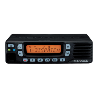
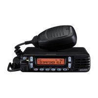
| Model | NX-800 |
| Category | Transceiver |
| Language | English |