Do you have a question about the Kenwood QR-666 and is the answer not in the manual?
Guide to unpacking the receiver, checking for damage, and verifying accessories.
Instructions for selecting a location and connecting power to the receiver.
Importance of antenna and grounding for reception, and types of antennas.
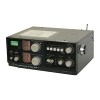
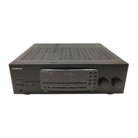
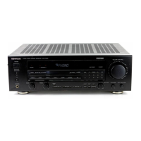
Detailed explanation of all controls located on the front panel of the QR-666 receiver.
Description of all controls and connectors located on the rear panel of the QR-666.
How to read and set frequencies using the main tuning and band spread dials.
Step-by-step guide for receiving AM broadcast and short-wave signals.
Instructions for tuning in SSB and CW signals, including BFO adjustment.
Information on operating the receiver using batteries or external DC power.
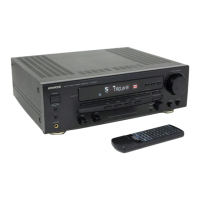
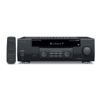
Details on connecting external devices using the remote socket and its pin functions.
Overview of the QR-666's circuit design and block diagram.
Detailed explanation of the RF amplifier circuit and its components.
Description of the mixer circuit, including frequency conversion.
Explanation of the local oscillator circuit for stable frequency generation.
Details on the second mixer and IF amplifier stages for F band conversion.
Explanation of the 2-stage IF amplifier and its selectivity features.
Description of the AGC amplifier and S meter circuitry.
Explanation of AM, CW/SSB detector circuits and the ANL function.
Details of the audio frequency amplifier stages and power output.
Explanation of the 9V power regulator circuit for stable operation.
Description of the power supply, pilot lamps, and battery/AC changeover.
Instructions for safely removing the receiver's cabinet for servicing.
How to position the receiver for easier maintenance and adjustment.
Setup procedures and control settings before performing adjustments.
Steps for adjusting the receiver using a signal generator.
How to adjust the receiver using a marker generator or broadcast signal.
Procedure for adjusting the BFO frequency for optimal reception.
Step-by-step guide for replacing and stringing the dial cord.
Instructions for replacing fuses and pilot lamps.
How to change the power voltage setting for different regions.
Guidelines for ordering and using replacement parts.
Information on installing optional marker and FM units.
Overview of common problems and their causes/remedies, not due to defective components.
Table of transistor operating voltages for diagnostic purposes.