Do you have a question about the Kenwood RX-28 and is the answer not in the manual?
Components for receiving AM/FM signals and related accessories.
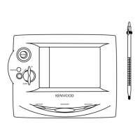
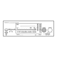
Unit for remote operation of the receiver.
Diagram showing buttons and functions of the remote control.
List of available instruction manual languages and their codes.
Procedure to detach the front panel from the unit.
Steps for removing various PCBs like headphone, power transistor, and tuner.
Overview of audio signal processing from input to output.
Block diagram showing control signals and microprocessor interaction.
Block diagram detailing the amplifier circuit's signal paths.
Block diagram illustrating the tuner circuit's signal paths.
Overview of the receiver's capabilities and features.
How operating conditions vary by destination model.
Default settings when the unit is turned on or reset.
Table showing preset frequencies during the reset process.
Instructions for entering and using the unit's test modes.
Diagram of the key matrix and input scanning logic.
Block diagram of microprocessor connections to other units.
Visual representation of the microprocessor's pin assignments.
Detailed description of pins related to display segments and grids.
Description of control, interface, and special function pins.
Detailed functions of serial data and clock pins.
Functions of control, mute, and key return pins.
Diagram showing pin assignments for the deck microprocessor.
Functions of tone, record level, and reset pins.
Description of tape selection and mute control pins.
Functions of pins controlling mechanism operation and speed.
Pins for system control, data, busy, power, and mute.
Table summarizing initial conditions for various functions.
Detailed procedures for various test modes.
Procedure to improve timer accuracy by component replacement/addition.
Method for adjusting frequency using a high-impedance buffer and counter.
Method to calculate monthly timing error based on frequency measurements.
Procedures for demagnetizing, cleaning heads, and setting azimuth.
Steps for adjusting tape speed for Hi-Speed and Normal modes.
Procedures for adjusting playback level and bias current.
Adjustments for FM discriminator, distortion, and separation.
Procedure to adjust tuning levels for FM and AM bands.
Procedures for demagnetizing, cleaning, and azimuth adjustment.
Adjusting tape speed for Hi-Speed and Normal modes.
Adjusting playback level and bias current.
Adjustments for FM discriminator, distortion, and crosstalk.
Adjusting tuning levels for FM and AM bands for FL201 indicator.
Procedures for demagnetizing, cleaning, and azimuth adjustment.
Adjusting tape speed for Hi-Speed and Normal modes.
Adjusting playback level and bias current.
Adjustments for FM discriminator, distortion, and separation.
Adjusting tuning levels for FM and AM bands for FL201 indicator.
Diagram showing how major units and connections are wired together.
Component placement on the display unit PCB.
Component placement on the tuner unit PCBs.
Further component placement details for the display unit PCB.
Component placement on the record/playback amp unit PCB.
Component layout for the volume and balance control board.
Component layout for the MIC mixing and MIC boards.
Component layout for the power supply and voltage selector board.
Component placement on the record/playback amp unit PCB.
Further component placement for the record/playback amp unit PCB.
Schematic diagrams for tuner and FM/AM sections.
Schematic diagrams for amplifier and cassette deck sections.
Schematic diagrams for microprocessor and control circuits.
Schematic diagrams for power supply and display circuits.
Schematic diagrams for various other circuit sections.
Detailed exploded view of the cassette mechanism parts.
Indication of points requiring lubrication in the mechanism.
Exploded view showing the assembly of the main unit.
Exploded view of front panel controls and assembly.
Exploded view of chassis and internal component assembly.
Table of unit assemblies categorized by destination.
List of parts for the tuner unit, categorized by destination.
List of parts for the display unit and miscellaneous components.
Further parts list for the tuner unit components.
Further parts list for the display unit components.
List of parts for the record/playback amp unit.
Continued list of parts for the record/playback amp unit.
Further parts list for the record/playback amp unit.
List of various components like capacitors, connectors, and inductors.
List of parts for connectors, diodes, and transistors.
List of integrated circuits and transistors used in the unit.
List of transistors and parts for the mechanism assembly.
List of parts specific to the mechanism assembly.
List of mechanism parts, belts, and springs.
Table of unit assemblies categorized by destination country.
List of parts referenced by number, including new parts and warranty items.
Technical specs for amplifier, MW, LW, and FM tuner sections.
Specs for cassette deck, heads, motors, and general unit details.
Technical specs for amplifier, AM, and FM tuner sections for US/Canada.
Specs for cassette deck, heads, motors, and general unit details for US/Canada.
| Brand | Kenwood |
|---|---|
| Model | RX-28 |
| Category | Stereo Receiver |
| Language | English |