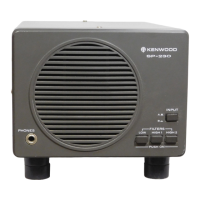
Do you have a question about the Kenwood SP-120 and is the answer not in the manual?
Details on specific components used in the TS-120S transceiver.
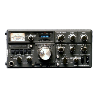
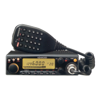
Highlights of the TS-120S transceiver's capabilities and design.
Overview of the TS-120S, including its single-conversion system and PLL circuitry.
Technical specifications for the optional YK-88C CW filter.
Explanation of the signal path and components during reception.
Description of the signal path and components during transmission.
How the TS-120S generates and manages frequencies using PLL.
Detailed explanation of the Phase Locked Loop circuit functionality.
Description of the Carrier Oscillator and its role in frequency generation.
Functionality of the digital frequency counter system.
Description of the Variable Frequency Oscillator circuit.
Diagram illustrating the internal connections of the counter circuit.
Explanation of circuits designed to protect the transceiver.
Details on the function and components of the filter unit.
Description of the final stage amplifier and its protection features.
Component layout and schematic for the RF Unit.
Component layout and schematic for the IF Unit.
Component layout for the Switch (B) Unit.
Component layout for the Switch (A) Unit.
Component layout for the Relay Unit.
Component layout for the AF, GEN Unit.
Schematic diagram for the PLL Unit.
Schematic diagram for the Counter Unit.
Schematic diagram for the Counter Unit.
Component layout for the VFO Unit.
Component layout for the Carrier Unit.
Component layout for the Filter Unit.
Component layout for the Filter Unit.
Component layout and schematic for the Final Unit.
Instructions for removing the counter unit from the transceiver.
Procedure for removing the final unit assembly.
Troubleshooting guide for receiver output and noise issues.
Troubleshooting guide for transmitter power output and operational issues.
Troubleshooting guide for issues related to the digital counter display.
Troubleshooting common issues like power supply, S-meter, and ALC.
Troubleshooting guide for issues related to the PLL system.
General guidelines and test equipment requirements for adjustments.
List of necessary equipment for performing adjustments.
Steps required before starting the adjustment procedures.
Adjustment procedure for the Transmit Band Pass Filter.
Adjustment procedure for the Receive Band Pass Filter.
Adjustment procedure for the Intermediate Frequency amplifier.
Adjustment procedure for the IF trap circuit.
Adjustment procedure for the Noise Blanker.
Adjustment of the counter's standard oscillator.
Adjustment of the base current for the transmitter.
Procedure to adjust and minimize carrier suppression.
Adjusting the carrier point for proper signal transmission.
Adjustment procedure for the side tone circuit.
Procedure for adjusting the IC meter reading.
Adjustment of the Automatic Level Control circuit.
Adjustment related to the protection circuits.
Procedure for adjusting the S-meter calibration.
Technical details of the PS-30 power supply unit.
Schematic for the IF Unit.
Schematic for the Counter Unit.
Schematic for the PLL Unit.
Schematic for the AF GEN Unit.
Schematic for the RF Unit.
Schematic for the Final Unit.
Schematic for the Car Unit.
Schematic for the VFO Unit.
| Brand | Kenwood |
|---|---|
| Model | SP-120 |
| Category | Transceiver |
| Language | English |