Do you have a question about the Kenwood SP-180 and is the answer not in the manual?
General specifications including frequency range, mode, and power requirements.
Receiver sensitivity, rejection, selectivity, and audio output specifications.
Transmitter input power, impedance, suppression, and response specifications.
Four tunable memories, split-frequency operation, and memory shift features.
Details on high power output, reliability, and protection circuits.
Frequency coverage, WARC allocations, and WWV reception.
Features of the digital display, including frequency and difference display.
Detailed description of the TS-180S receiver section's signal path.
Detailed description of the TS-180S transmitter section's signal path.
Si NPN Epitaxial Planer Transistor absolute maximum ratings.
Absolute maximum ratings and application for 2SK125 JFETs.
Absolute maximum ratings and application for SRF 1714 transistors.
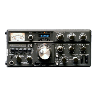
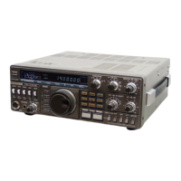
Identification and layout of controls and indicators on the front panel.
Identification of connectors and ports on the rear panel.
Internal layout of major circuit boards viewed from the top.
Internal layout of major circuit boards viewed from the bottom.
Circuit diagram for the RF unit, showing component layout and connections.
Circuit diagram for the Coilpack unit, detailing inductors and switches.
Circuit diagram for the IF unit, illustrating signal processing stages.
List of capacitor types, part numbers, and values.
List of resistor types, part numbers, and values.
List of semiconductor devices, part numbers, and types.
List of essential test equipment for calibration and alignment procedures.
Procedures for adjusting receiver sensitivity and frequency accuracy.
Procedures for adjusting VFO scale accuracy and output voltage.
Procedure for adjusting the transmitter band-pass filter waveform.
Table mapping connector numbers to PC board and parts names.
Identification of external components of the VFO-180 unit.
Specifications for the VFO-180 unit including frequency and voltage.
Block diagram illustrating the VFO ASS'Y unit and its connections.
Power supply specifications including input, output, and dimensions.
Identification of external components of the PS-30 power supply.
Specifications for the AT-180 antenna tuner.
Identification of external components of the AT-180 antenna tuner.
List of instruments required for power meter adjustment.
Procedure for adjusting the power meter output.
| Brand | Kenwood |
|---|---|
| Model | SP-180 |
| Category | Transceiver |
| Language | English |