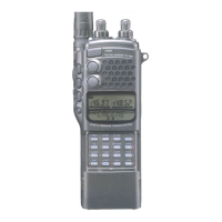
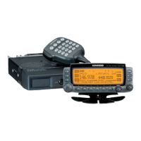
Do you have a question about the Kenwood TH-78E and is the answer not in the manual?
Explains the frequency configuration for VHF and UHF bands.
Details the receiver system architecture and components.
Covers audio circuits, including AFV and AFU.
Details the transmitter system, including VCO and modulation.
Details the power supply circuit and its distribution.
Describes the Phase Locked Loop (PLL) circuit.
Covers microcomputer functions and associated circuits.
Explains DTMF and DTSS/PAGING functionalities.
Describes the Continuous Tone-Coded Squelch System (CTCSS) operation.
Lists and describes components of the control unit.
Lists and describes components of the TX-RX unit.
Lists components for the PA+EL module unit.
Lists components for the VCO unit.
Provides pin functions and block diagram for PLL IC.
Details pin functions and block diagram for FM Receive IC.
Provides pin names, functions, and pin layout for electronic volume IC.
Shows pin connection and I/O port specifications for the microcomputer.
Provides pin layout and pin functions for the microcomputer.
Lists parts for the main TH-78 unit.
Lists parts for the control unit.
Lists parts for the TX-RX unit.
Lists parts for the SUB UNIT (V, U, V.U).
Lists parts for the MODULE UNIT (PA + EL).
Provides an exploded view of the unit for disassembly.
Provides an exploded view of the unit for disassembly.
Illustrates the packing configuration of the product.
Lists the necessary test equipment for adjustments.
Outlines the preparation steps before making adjustments.
Details common adjustments for the TX-RX unit.
Describes the adjustment procedure for the PLL circuit.
Details the adjustment steps for UHF receiver sensitivity and squelch.
Details adjustment procedures for VHF receiver sensitivity and squelch.
Details adjustment procedures for UHF transmitter power and deviation.
Details adjustment procedures for VHF transmitter power and deviation.
Shows the block diagram for the TX-RX unit.
Shows the block diagram for the CONTROL UNIT.
Shows the block diagram for the TX-RX unit.
Illustrates signal levels within the radio circuits.
Details signal levels in the Intermediate Frequency (IF) stages.
Lists terminal functions for the Control Unit.
Lists terminal functions for the 16 Key FPC.
Lists terminal functions between Control Unit and TX-RX Unit.
Provides specifications for the BT-8 battery case.
Lists the parts included in the BT-8 battery case.
Details electrical and microphone specifications for HMC-2.
Lists the parts for the HMC-2 headset.
Lists the parts for the ME-1 extension memory unit.
Shows external view and dimensions for the PG-2W DC cord.
Shows the circuit diagram for the PG-3F plug with cord.
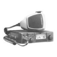
Shows external views of soft case, bracket, and waterproof case.
Lists the parts for the MB-6 mobile bracket.
Shows external views and specifications for SMC-31 and SMC-32.
Lists the parts for SMC-31 and SMC-32.
Details electrical and microphone specifications for SMC-33.
Shows the external view of the HS-9 earphone.
Lists the parts for the SMC-33 speaker microphone.
Shows the component side PC board view of the TSU-7.
Lists the parts for the TSU-7 CTCSS unit.
Provides the circuit diagram for the TSU-7 CTCSS unit.
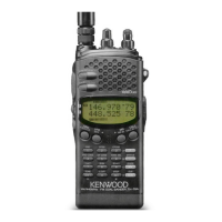
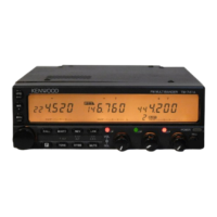
Lists general specifications like frequency, dimensions, and weight.
Details transmitter specifications including power and modulation.
Details receiver specifications including frequency, sensitivity, and audio output.
| Modulation | FM |
|---|---|
| Channels | 200 |
| Supply voltage | 7.2 VDC |
| Antenna Connector | BNC |
| Frequency Range | 144-146 MHz, 430-440 MHz |
| Receiver Sensitivity | 0.16 µV for 12 dB SINAD |
| Channel spacing | 25 kHz |
| Battery | 7.2V Ni-MH battery pack |
| Weight | 350g (including battery) |