Do you have a question about the Kenwood TK-701S and is the answer not in the manual?
Critical safety precautions to be followed during operation and servicing of the radio.
Basic steps for operating the radio controls and indicators.
Instructions for unpacking the radio and information on licensing requirements.
Recommended checks to ensure proper operation before final installation.
Guidance on planning the physical installation of the radio and its components.
A flowchart detailing the process for dealer sales and initial setup.
Procedures for writing frequencies into PROM and performing initial setup.
Steps for modifying the transceiver for duplex, simplex, 16CH, 32CH, and installing signaling.
Instructions for installing the time-out timer and performing frequency realignment.
Detailed description of the transmitter's signal path and circuitry.
Detailed description of the receiver's signal path and circuitry.
Explanation of the common Phase-Locked Loop circuit's operation and components.
Explanation of the Phase-Locked Loop circuit specific to the transmitter.
Descriptions of modulator, PLL unlock, QTD invert, frequency shift, and diode matrix circuits.
Diagram illustrating the signal flow within the transmitter section.
Diagram illustrating the signal flow within the receiver section.
Instructions for removing the radio's case, covers, and front panel.
Steps for removing the TX-RX unit, including shield and connector disconnections.
Instructions for removing the PLL unit and speaker.
Procedures for replacing LEDs and lamps.
Instructions for replacing channel switches and setting limit screws.
Procedures for initial setup, PLL lock voltage, and TCXO frequency adjustment.
Steps for adjusting receiver sensitivity and squelch threshold.
Procedures for adjusting transmitter power, frequency, deviation, and spurious emissions.
Instructions for setting up and using the monitor function for testing.
Diagrams and lists of parts related to the disassembly process.
Block diagram illustrating the overall radio circuit architecture.
Detailed schematic diagrams of the radio's electronic circuits.
Comprehensive list of parts used in the PLL unit.
Comprehensive list of parts used in the TX-RX unit.
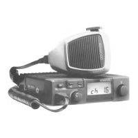
| Power Output | 25W |
|---|---|
| Weight | 1.4 kg |
| Modulation | FM |
| Frequency Range | 148-174 MHz |
| Frequency | 148-174 MHz |
| Dimensions | 160(W) x 53(H) x 169(D) mm |