Do you have a question about the Kenwood TK-2207 and is the answer not in the manual?
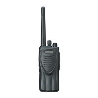
| Frequency Range | 136-174 MHz |
|---|---|
| Number of Channels | 16 |
| Channel Spacing | 12.5/25 kHz |
| Power Output | 5W |
| Battery Life | 9 hours (with KNB-29N) |
| Weight | 360 g (with KNB-29N) |
| Modulation | 16K0F3E / 11K0F3E |
| Operating Voltage | 7.5 V DC |
| Operating Temperature | -30°C to +60°C |
Manual intended for experienced technicians with service information for equipment.
Guidelines for ordering replacement parts or equipment information.
Important safety precautions for personnel handling the equipment.
Lists different operating modes for the transceiver.
Instructions on how to enter each operating mode.
Details on PC mode, connection, and KPG-22 interface cable.
Description of the KPG-87D programming software.
Overview of the clone mode for copying transceiver data.
Example illustrating how to copy programming data via RF communication.
Step-by-step instructions for operating the clone mode.
Steps to remove the case assembly from the transceiver chassis.
Procedure for removing the TX-RX unit from the chassis.
Steps to remove the battery release lever from the case assembly.
Procedure for attaching the battery release lever to the case assembly.
Steps to assemble the battery release lever.
Important precautions and steps for assembling components correctly.
Procedure for mounting the chassis to the case assembly.
Steps to attach the antenna receptacle to the chassis.
Information about nuts for volume and channel knobs and removal jig.
Details the frequency configuration of the receiver.
Describes the receiver's front end and first mixer circuits.
Explains the IF amplifier circuit and its function.
Describes the circuit for switching between wide and narrow modes.
Details the audio amplifier circuit and speaker output.
Explains the squelch circuit operation for controlling sound output.
Describes signalling protocols like QT/DQT, MSK, and DTMF.
Explains the PLL circuit for generating oscillator and RF signals.
Details the VCO operation in transmit and receive modes.
Function of the unlock detector for transmitter disabling.
Overview of the transmitter system, including microphone amplifier.
Describes the drive and final amplifier stages of the transmitter.
Explains the Automatic Power Control (APC) circuit.
Details encode signalling protocols like QT/DQT.
Details the different 5V power supplies for the microprocessor.
Explains the control circuit managed by the microprocessor.
Describes the circuit for shifting frequency based on the microprocessor.
Describes the memory circuit consisting of CPU and EEPROM.
Explains the low battery warning system and indicators.
Details the control system involving keys and channel selector inputs.
Describes the pin functions for connector CN401.
Details the pin functions for the microprocessor (IC405).
Lists and describes components within the TX-RX unit.
Lists and describes components on the additional PCB.
Lists parts for the TK-2207 model.
Lists parts specifically for the TX-RX unit.
Lists test equipment needed for performing alignment procedures.
Information on the SMA terminal and required adapter for adjustment.
Details on the repair jig for TK-2207 chassis and voltage checks.
Usage and precautions for the battery jig during adjustment.
Identifies adjustment points on the TX-RX unit component and foil sides.
Details frequency and signalling settings for the transceiver.
Steps and requirements for preparing the transceiver for tuning.
Diagram showing component placement on the TX-RX unit.
Diagram showing components on the additional PCB.
Diagram showing component placement on the foil side of the TX-RX unit.
Overall schematic diagram for the TX-RX unit.
Block diagram illustrating the functional units of the TX-RX unit.
External view, specifications, and schematic for the rapid charger.
External view, specifications, and schematic for the Ni-MH battery pack.
Specifications and schematic for the Ni-Cd battery pack.
External view and specifications for the belt clip.
General operating parameters like frequency, channels, voltage, and environment.
Performance specifications for receiver sensitivity, selectivity, and audio output.
Performance specifications for transmitter power, modulation, and noise.