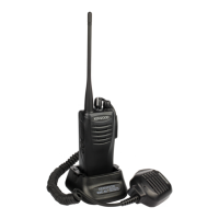
Do you have a question about the Kenwood TK-2402(V) and is the answer not in the manual?
| Channels | 16 |
|---|---|
| IP Rating | IP54 |
| Frequency Range | 136-174 MHz |
| Power Output | 5W |
| Operating Temperature | -30°C to +60°C |
| Channel Spacing | 12.5/25 kHz |
Defines manual's purpose and how to order replacement parts.
Essential safety guidelines for operating and servicing the equipment.
Guidance on servicing procedures and component identification.
Steps for initial setup and programming of the transceiver.
Instructions on how to access different operational modes.
Details on connecting and configuring the transceiver for PC communication.
Explanation of the wireless data transfer capability.
Step-by-step guide for cloning transceiver data wirelessly.
Instructions for disassembling the main chassis, case, and holder.
Steps to detach the TX-RX unit and remove the battery release lever.
Description of the transceiver's frequency generation and PLL circuit.
Explanation of the receiver signal path and key components.
Details on intermediate frequency amplification and audio signal processing.
Description of the transmitter signal path, microphone, and audio processing.
Explanation of power amplification stages, APC, and control circuitry.
Description of the TCXO, VCO, and PLL-IC for frequency generation.
Overview of the MCU and its peripheral circuits for transceiver control.
Functions related to frequency shift, memory, battery status, and key inputs.
Details on QT, DQT, DTMF, MSK encoding and decoding.
Description of various voltage rails and their sources within the transceiver.
Detailed pinout and function description for the microcontroller.
List and description of components found on the TX-RX unit.
List of parts specific to different transceiver models.
Detailed parts list for the TX-RX unit with part numbers.
Diagram showing the exploded assembly of the transceiver unit.
List of items included in the packing for specific models.
List of items included in the packing for the TK-2407 model.
List of test equipment and initial setup for transceiver alignment.
Information on antenna adapters and specialized repair/battery jigs.
Table of frequencies and signaling types used for adjustment.
Pre-tuning requirements including power supply and dummy load setup.
Procedures for adjusting transmitter frequency and output power levels.
Steps for tuning DQT, QT, and deviation parameters.
Procedure for semi-automatic adjustment of receiver sensitivity.
Diagram showing the component layout on the TX-RX unit's front side.
Diagram showing the circuit trace layout on the TX-RX unit's foil side.
Detailed electrical schematic for the TX-RX unit.
High-level functional block diagram of the TX-RX unit.
Signal level chart for the receiver signal path.
Signal level chart for the transmitter signal path.
Overall operating parameters including frequency, voltage, and dimensions.
Detailed performance metrics for the receiver section.
Detailed performance metrics for the transmitter section.
 Loading...