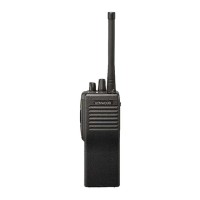
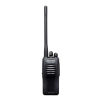
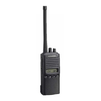
VHF FM TRANSCEIVER
TK-250
SERVICE MANUAL
I REVISED I
KENWOOD
© 1995-4 PRINTED IN JAPAN
B51-8279-20 (B) 1558
This service manual is the same as the service manual
(851-8279-10) for TK-250 (K , K2, Mand M2 destina-
tions ) except th at th is manual contains new items (T, E
destinations).
Use it together with the previous service manual (851-
8279-10).
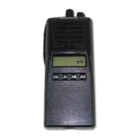
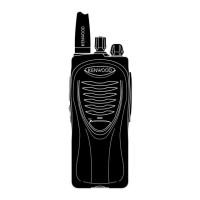
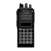
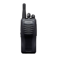
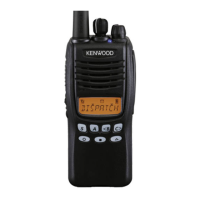
Knob(PTl)
(K29-4917 -02) --
Dressing panel
(A21-1544-03)
*Refer to parts list on page 33.
Antenna
(T90-
*)
Knob(CHANNEL SELECTOR)
(K29-4920-03)
Knob(VOLUME)
(K29-4918-03)
Badge
(B43-11oo-04)
Cabinet
-- (A02-1829-01)
CONTENTS
GEN ERAL •.......•.•.•.••..•............•.•••..•.•........•••..•.••.•...•.... 2
DISASSEMBL Y FOR REPAIR •.•.•..•.•..........•..•.••.•....... 3
INST ALLA TION .•........•.•.•.•.••.•....•.....•.•.••.•.•••.•......•.•.••. 5
REALIGNMENT .••..•.•.•.......•.•.••••..•.•..•.•..•...•.•.•.•.••....... 8
CIRCUIT DESCRIPTION •.•••...•.•...••..•••.•.•.....•.••.•.•..••.. 16
SEMICONDUCTOR DATA .....•.•.•..•.•.•.•..........••.•.•.•.... 24
DESCRIPTION OF COMPONENTS •..•.•.•......•...••.•.•.•. 31
PARTS LIST ..•.•..••.••.•.........•.•.••..•..•.........•.•..•.•..•........• 33
EXPLODED ViEW •..•.•.••.............•..•.•.•.............•.•.••..•... 40
PACKING ...•.•............••••.•...•.......•..•....••..•.•...........•.•.•.• 42
TERMINAL FUNCTION •.••.•.•............•.•.•..•.•...........•.••. 43
ADJUSTMENT ...•.•........•.•.••...•.•..........•.••••.•.•.•.•......•.•• 46
PC BOARD VIEWS
VCO UNIT(X58-4130-10) •..•.•........••••••••.•.•.•.••..•.•••. 51
VCO UNIT(X58-4290-50) .....•.•.•..•.•.••.•.•.......••.•.•.•.. 52
TX-RX UNIT(X57-444X-XX) (A/3) ........•.•.•.•.•.•....... 53
TX-RX UNIT(X57-444X-XX) (B/3) ...•.••••.•.•.•.•........• 57
TX-RX UNIT(X57-4442-71) (A/3) •.•.•.•.•••.•.•.......•.••. 61
TX-RX UNIT(X57-4442-71) (B/3) •.•.........•.•.•.•.•.•..•. 65
TX-RX UNIT(X57-444X-XX) (C/3) ..........•.•.•.•........• 69
SCHEMATIC DIAGRAM .....•.••.•.•.•.•.••.........•••.•.•.••••..•. 73
BLOCK DIAGRAM .........•..•.•.•.•.••.•..........•.•.•.•..••.•....... 81
LEVEL DIAGRAM ......•..••.••.•..•.•••........•..•.•.•.•.•.........••• 83
KDM-7(DTMF KEY PAD) •.•.•.•.•...........••••.••.•.••..•......•. 84
KHS-1 (HEAD SET WITH VOX
& PTT) •.•.•.••••..•......••• 84
KSC-76 (MULTIPLE RAPID CHARGER) •.•..•.•........••. 86
KSC-8 (COMPACT CHARGER) •••.•.•.•.........••.••••..•.••.• 89
KSC-86 (MULTIPLE CHARGER) •..•........•..•...•.•.•..•.•.. 90
KNB-11 A/12A(Ni-Cd BA TTERY) •..••....•......•.•••..•••.•.•. 93
KPG-22(PC PROGRAM INTERFACE) •..•.•.•.••••.•......•• 93
SPECIFICATIONS ..•.•.•.•.•.•.•.•.•............ BACK COVER
CAUTION :
When using an extemal power connector, please use with maximum final module
protection of 9V.