EasyManua.ls Logo

Kenwood TK-3107 Service Manual

Kenwood TK-3107
28 pages
To Next Page IconTo Next Page
Page #1 background imageLoading...
Page #1 background image
© 2000-2 PRINTED IN JAPAN
B51-8572-00(S) 141
TK-3107
GENERAL.................................................................. 2
REALIGNMENT......................................................... 2
DISASSEMBLY FOR REPAIR................................... 4
CIRCUIT DESCRIPTION ........................................... 5
SEMICONDUCTOR DATA ......................................... 8
DESCRIPTION OF COMPONENTS.......................... 9
PARTS LIST............................................................. 10
EXPLODED VIEW ................................................... 17
PACKING ................................................................. 18
ADJUSTMENT......................................................... 19
PC BOARD VIEWS
TX-RX UNIT (X57-6030-11) ................................ 23
SCHEMATIC DIAGRAM .......................................... 29
BLOCK DIAGRAM .................................................. 33
LEVEL DIAGRAM ................................................... 35
KNB-15A (Ni-Cd BATTERY) ................................... 36
SPECIFICATIONS ................................BACK COVER
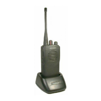
Antenna
(T90-0694-15)
Cabinet assy
(A02-2448-13)
Knob(VOLUME)
(K29-5255-03)
TK-3107 (16 channels)
CONTENTS
Knob
(CHANNEL SELECTOR)
(K29-5278-03)
UHF FM TRANSCEIVER
SERVICE MANUAL
M2 version

Other manuals for Kenwood TK-3107

Questions and Answers:

Kenwood TK-3107 Specifications

General IconGeneral
frequency range470-490 MHz
RF power output4W
number of channels16CH
Power IconPower
operating voltage7.5 VDC ± 20 %
Operating Environment IconOperating Environment
temperature range-30 °C to + 60 °C (-22 °F to + 140 °F)
Weight and Dimensions IconWeight and Dimensions
dimensions with battery58 W X 125.5 H X 35 D mm
weight with battery380g (0.83lbs)

Summary

GENERAL

Introduction, Safety, and Familiarization

Manual overview, parts ordering, safety precautions, and device controls.

REALIGNMENT AND PROGRAMMING

Operational Modes and PC Setup

Explains operational modes and the PC programming setup for realignment.

DISASSEMBLY AND CIRCUIT DESCRIPTION

Disassembly Procedures

Instructions for separating case, chassis, and removing the lever.

Circuit Description Overview

Covers receiver, transmitter, squelch, PLL, APC, and control circuits.

COMPONENT DATA AND PARTS LIST

Semiconductor Data

Lists pinouts and ratings for microprocessor, transistors, and FETs.

Parts List Overview

Details general capacitors, resistors, and TX-RX unit components.

ASSEMBLY, PACKAGING, AND ADJUSTMENT

Exploded View and Packaging

Illustrates exploded view and details packaging procedures.

Adjustment Procedures

Lists required test equipment and outlines adjustment procedures.

Related product manuals