EasyManua.ls Logo

Kenwood TK-7302 Service Manual

Kenwood TK-7302
52 pages
To Next Page IconTo Next Page
Page #1 background imageLoading...
Page #1 background image
This product uses Lead Free solder.
This product complies with the
RoHS
directive for the European market.
© 2009-9 PRINTED IN JA PAN
B51-8886-00
(
N
)
000
SERVICE MANUAL
VHF FM TRANSCEIVER
CONNECTION CABLE
TK-7302/7302
(
V
)
TK-7302H/7302H
(
V
)
KCT-60
GENERAL .....................................................2
SYSTEM SET-UP .........................................4
REALIGNMENT ...........................................4
INSTALLATION ............................................6
DISASSEMBLY FOR REPAIR ......................8
CIRCUIT DESCRIPTION ............................10
SEMICONDUCTOR DATA .........................15
COMPONENTS DESCRIPTION .................16
PARTS LIST ...............................................17
EXPLODED VIEW ......................................26
PACKING ....................................................27
ADJUSTMENT ..........................................28
TERMINAL FUNCTION .............................34
PC BOARD
DISPLAY UNIT (X54-3670-20) ...............36
TX-RX UNIT (X57-7680-XX) ..................38
SCHEMATIC DIAGRAM ............................42
BLOCK DIAGRAM .....................................48
LEVEL DIAGRAM ......................................50
OPTIONAL ACCESSORIES
KCT-60 (CONNECTION CABLE) ............51
SPECIFICATIONS ...................BACK COVER
CONTENTS
Panel assy
(A62-1171-03)
Badge
(B43-1629-04)
Key top
(K29-9448-01)
Modular jack
(E58-0535-05)

Other manuals for Kenwood TK-7302

Question and Answer IconNeed help?

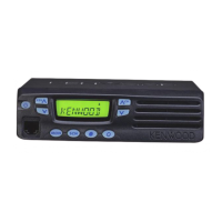
Do you have a question about the Kenwood TK-7302 and is the answer not in the manual?
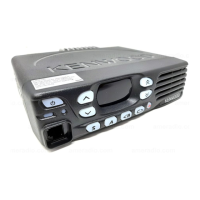
Kenwood TK-7302 Specifications

General IconGeneral
TypeMobile transceiver
Frequency Range136-174 MHz
Channel Capacity128
Number of Channels16
Modulation16K0F3E/11K0F3E
Operating Temperature-30°C to +60°C
RF Output Power25W
Channel Spacing25 kHz/12.5 kHz
Operating Voltage13.8 V
Voltage13.8 V

Summary

DISASSEMBLY FOR REPAIR

Disassembly Procedure for Repair

Step-by-step guide for dismantling the transceiver for repair.

CIRCUIT DESCRIPTION

ADJUSTMENT

Test Equipment for Alignment

Lists essential test equipment and their major specifications for alignment.

Transmitter Section Adjustments

Details adjustments for frequency, high power, low power, and deviation.

TERMINAL FUNCTION

SPECIFICATIONS

General Specifications

Covers frequency range, channels, voltage, dimensions, and weight.

Receiver Specifications

Details sensitivity, selectivity, and intermodulation based on EIA/TIA-603.

Transmitter Specifications

Lists RF power output, spurious response, and modulation details.

Related product manuals