Do you have a question about the Kenwood TK-780H and is the answer not in the manual?
| Frequency Range | 136-174 MHz |
|---|---|
| Channel Capacity | 128 channels |
| Operating Temperature Range | -30°C to +60°C |
| RF Output Power | 45 W |
| Channel Spacing | 12.5 kHz / 25 kHz |
| Power Supply | DC 13.8V |
| Modulation | FM |
| Voltage Range | 13.6 V DC ±15% |
Provides an overview of the manual's scope and intended audience.
Details the process and required information for ordering parts.
Outlines essential safety precautions for operating the equipment.
Lists essential checks and considerations before installing the radio.
Instructions for unpacking and verifying radio accessories.
Explains federal regulations and licensing for radio installation.
Describes procedures for checking radio operation before installation.
Guidance on planning the physical installation of the radio.
Inspects the environment and plans cable runs for safe installation.
Guidelines for selecting an antenna location and ensuring proper grounding.
Advice on mounting the radio securely and ensuring adequate air cooling.
Instructions for connecting DC power, including polarity and connection points.
Covers antenna systems and radio location for control stations.
Guidance on selecting an appropriate antenna system for control stations.
Recommendations for placing the control station radio for optimal performance.
Refers to diagrams and procedures for servicing the radio.
Introduces the radio's operational features and programmable functions.
Describes the trunking mode capabilities and programming.
Details the conventional mode capabilities and programming.
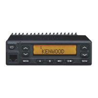
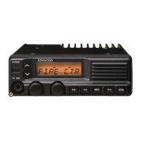
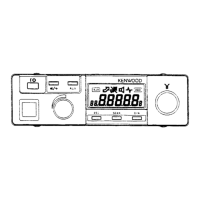
Explains the function of front panel keys, LEDs, and displays.
Describes the functions of individual front panel push buttons.
Lists and explains functions assignable to programmable keys.
Details functions assignable to keys in conventional mode.
Details functions assignable to keys in trunking mode.
Explains the auto telephone interconnect feature for trunking systems.
Describes the function of the AUX-A key and its effect on the AUX port.
Explains the AUX-B key function, applicable when the voice scrambler is not installed.
Describes the channel increment/decrement function in conventional mode.
Explains the function to automatically send DTMF ID at the beginning of transmission.
Explains the function to automatically send DTMF ID at the end of transmission.
Describes how this key switches LCD display content between system/group numbers and names.
Explains how to activate the emergency mode and its parameters.
Describes how to use the FCN key to activate programmed functions via DTMF.
Explains the group number increment/decrement function.
Describes how to switch to the pre-programmed home channel.
Explains how to select a preset system/group.
Details how the horn alert function is activated and provides external alerts.
Explains how the key lock restricts button access to specific functions.
Describes how to enter the message mode for alphanumeric paging.
Explains how to recall DTMF memory data for stored numbers and text.
Describes the use of the monitor function for squelch or signalling release.
Explains how to switch and select OST tone pairs for conventional mode.
Details how to amplify microphone audio for PA speaker output.
Explains how to transmit the last transmitted DTMF code.
Describes how to start and stop scanning channels.
Explains how to toggle channels between inclusion and exclusion from scan.
Describes how to temporarily delete a scanned system.
Explains how to activate/deactivate scramble and enter code selection.
Describes how to send GPS data when the optional receiver is installed.
Explains how to increment/decrement system numbers in trunking mode.
Describes how to use the receive frequency for transmission without a repeater.
Explains how to end an RIC connection in trunking mode.
Describes how to adjust the audio volume level.
Explains the assignment of the "None" function to a key for simplicity.
Explains the function of various displays and indicators on the front panel.
Describes what the sub display shows, including system, channel, and function numbers.
Explains when the P indicator appears, signifying priority channel operation.
Describes when the MON indicator lights up, indicating the Monitor button is pressed.
Notes that this icon is not used on this transceiver.
Explains when the SCN indicator appears, signifying scan mode activation.
Describes when the AUX indicator appears, showing auxiliary function activation.
Explains when the handset indicator appears in trunking and conventional modes.
Describes when the MAIL indicator flashes or lights, related to status messages.
Explains what the alphanumeric display shows, including system/group names.
Identifies these keys as programmable function (PF) keys.
Details the operation of scanning in trunking and conventional formats.
Explains system scan and its types (Fix, List type) in trunking mode.
Describes how to lock out systems from the scan sequence.
Explains lockout selection via programming.
Details how users can lock out systems using a programmed key.
Explains the programmable time for scan resume after a call.
Describes the programmable time before scan resumes after transmission.
Explains different modes for reverting to a system or group.
Reverts to the system/group from which a call was received.
Reverts to the system/group based on the last PTT press and transmission.
Reverts to the system/group that was last selected while scanning.
Reverts to the selected system/group and enables talkback on the current group.
Time to stay with home repeater for monitoring data messages.
Explains group scan, including ID code decoding and group display changes.
Describes group scan behavior in conventional systems with QT/DQT and priority groups.
Details scan types (Single group, Multiple group) in conventional mode.
Scans all valid channels within the currently displayed group.
Scans all valid channels across all valid groups.
Specifies requirements for initiating a scan, such as non-priority channels.
Lists conditions that cause the scan to temporarily stop.
Explains the behavior of priority and non-priority channels during scanning.
Describes how to set a priority channel using programming software.
Explains scan behavior when no priority channel is set versus when one is set.
Details the function of the revert channel for transmitting during scanning.
The transceiver reverts to the priority channel.
Reverts to priority channel and enables talkback.
Reverts to the channel selected before scanning or changed during scan.
Reverts to the last channel that received a call during scan.
Reverts to the last transmitted channel during scan.
Reverts to selected channel and enables talkback.
Describes how to end a scan session.
Explains how to temporarily remove or add channels during a scan.
Provides detailed explanations for various radio features.
Covers common features applicable to both trunking and conventional modes.
Explains the TOT function to limit transmission duration and prevent continuous keying.
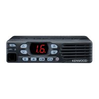
Describes the use of the 3-digit display for system, channel, or group numbers.
Explains how to configure the transceiver's LED for selective call alerts.
Details the PTT ID function for sending DTMF or MSK ANI with transmissions.
Explains how to set and use a radio password for security.
Describes how off hook decode affects signalling for calls.
Explains the automatic power-off feature, requiring ignition sense.
Provides detailed information on horn alert operation in trunking and conventional formats.
Explains the timing of the horn alert port output.
Describes how to set continuous horn alert by expiration time.
Explains whether QT/DQT is modulated with data transmission.
Details features specific to trunking operation.
Explains call indicator behavior for selectable and fixed IDs in trunking.
Describes the mode entered when a busy tone sounds during telephone interconnect.
Explains how the transceiver accesses other programmed systems automatically.
Details how transpond turns on/off for each group, sending data messages.
Explains how transmit inhibit blocks transmissions based on decoded ID codes.
Describes how to make a telephone interconnect call by assigning a key.
Explains ARQ mode for minimizing air traffic in data communication.
Details features specific to conventional operation.
Selects time for TOT pre-alert tone before TOT expiration.
Sets time transceiver cannot transmit after TOT exceeded.
Sets minimum wait time to reset TOT count after transmission.
Explains the OST function and its 16 tone pairs with 10-digit names.
Describes whether the OST code is memorized or not, defaulting to "off" if disabled.
Explains calling OST numbers directly using the keypad.
Prevents interference by waiting for channel open during transpond.
Details the use of DTMF/2-Tone and MSK for option signalling.
Explains DTMF and 2-tone decoding for individual, group, and DBD calls.
Describes how to select AND or OR logic for option signalling match conditions.
Explains how option signalling is automatically reset after a match.
Details how DBD codes affect transceiver operation, including TX inhibition.
Explains the MSK decoder for FleetSync signalling and squelch behavior.
Describes AND/OR logic for MSK signalling match conditions.
Introduces the KENWOOD proprietary FleetSync protocol for paging.
Explains the FleetSync protocol and its paging capabilities.
Describes how radio unit IDs are defined using Fleet and ID numbers.
Explains sending unique IDs (own) at the start/end of transmission.
Explains voice calls to individuals or groups using various call types.
Details limiting manual dial IDs to specific entered IDs.
Describes sending and receiving 2-digit status messages with alphanumeric characters.
Lists special status numbers and their reserved purposes.
Explains automatic response to status number requests from a base station.
Describes sending and receiving short messages (up to 48 characters).
Explains sending long messages (up to 1024 characters) via the COM port.
Details sending emergency status 99 and response options.
Explains selecting "Horn" or "Alert" as response to status 99.
Lists additional functions like manual dial and FleetSync baud rate.
Describes entering Fleet, ID, and Status numbers via DTMF keypad.
Explains setting the MSK data baud rate for communication.
Describes the delay timer for returning from message/stack mode to normal.
Explains transmitting status/short/long messages on data groups.
Explains enabling serial output for received status or PTT ID messages.
Describes displaying PTT ID on the LCD as Caller ID.
Explains providing a repeated alert tone until next operation.
Describes the beep sound after PTT ID (MSK) signaling is encoded.
Explains storing the last 3 received caller IDs in volatile memory.
Details sending GPS data automatically or upon request using ANMEA-0183 GPS.
Explains setting GPS data to send automatically or via poll.
Sets the time interval between automatic GPS data transmissions.
Sets the time from UTC zero minute to start GPS data transmission.
Describes pressing a key to send a single GPS data point.
Explains GPS data transmission on data groups in trunking and conventional formats.
Describes outputting selected GPS sentences via the radio serial port.
Details various parameters like GTC count, random access, retries, and wait times.
Sets the number of Go To Channel messages before transmitting data.
Explains using random access to avoid transmission crashes on busy channels.
Sets maximum retry transmissions when no acknowledgement is received.
Sets maximum time before giving up data transmission on busy channels.
Sets maximum time to wait for acknowledgement, used for retries.
Sets time from data reception end to acknowledgement start.
Time for unmodulated transmission to allow called unit to stop scanning or exit battery save.
Time from transmission start to data modulation start for data transmission.
Lists and describes the various tones used for user feedback.
Describes the tone output when the transceiver is turned on.
Explains the alert tone output for TX inhibition, battery warning, and PLL unlock.
Describes the transpond tone sounding when a D.B.D. code is received.
Describes the transpond tone sounding when a D.B.D. release code is received.
Describes the tone output when the correct password is entered.
Describes the tone output when the PTT switch is released.
Explains the busy tone in LTR and conventional modes for busy channels or TX inhibit.
Describes the tone for received group calls with DTMF/2-tone signalling.
Describes the tone for received individual calls with DTMF/2-tone signalling.
Describes the tone when a key is pressed or toggle function is turned on.
Describes the tone when a key is pressed or toggle function is turned off.
Describes tones for key presses, data storage, and mode changes.
Describes the tone for invalid key presses.
Describes the tone for the smallest system/group or group/channel.
Describes the tone for received calls with LTR/DTMF/2-tone signalling.
Indicates when the transceiver is out of range or cannot connect to the repeater.
Lists and describes the different operating modes of the transceiver.
Describes the standard mode for normal radio use.
Used by dealers to check fundamental characteristics of the radio.
Used for communication between the radio and a PC.
Used for reading/writing frequency data and other features via PC.
Used to transfer programming data from one radio to another.
Used for writing frequency, signalling, and features to the radio.
Provides instructions on how to access each of the transceiver's modes.
Refers to the ADJUSTMENT section for setting up Panel Test Mode.
Refers to the ADJUSTMENT section for setting up Panel Tuning Mode.
Covers procedures for realigning and reprogramming the transceiver.
Details using a PC, interface cable, and software for programming.
Introduces PC mode requirements and setup for programming.
Step-by-step guide for connecting the transceiver to a PC.
Describes the KPG-46 cable and its function in connecting to a computer.
Details the KPG-49D software for programming the radio.
Explains how to transfer and modify radio data using the PC.
Describes upgrading the transceiver's firmware.
Introduces the purpose of firmware programming for future upgrades.
Step-by-step guide for connecting the transceiver for firmware programming.
Details the procedure for programming new firmware into the transceiver.
Describes functions available during firmware programming, like speed changes.
Explains how to transfer programming data between radios using a cloning cable.
Details the steps to enter a password for cloning.
Instructs to power on the slave unit to receive cloned data.
Explains how to start data transfer from the master to the slave unit.
Describes the process for cloning multiple slave units sequentially.
Describes writing mode for frequency data and signalling, used for user equipment maintenance.
Step-by-step instructions to enter the self programming mode.
Explains how to set up each channel's action mode using panel keys.
Describes setting up all channels together in action mode using panel keys.
Explains how to clear settings or return the transceiver to its original default.
Provides instructions for installing the transceiver and its accessories.
Describes the KCT-19 cable for connecting external equipment.
Step-by-step instructions for installing the KCT-19 cable into the transceiver.
Details the function of each pin on the KCT-19 accessory port.
Describes the function of pins on the accessory terminal connectors.
Lists and explains the function of each terminal pin.
Explains jumper settings for data equipment connections.
Continues detailing accessory terminal pin functions.
Lists and explains the function of each terminal pin.
Describes terminals for optional boards and differences between schematic and PC board views.
Provides the schematic diagram for optional board terminals.
Shows the PC board layout for optional board terminals.
Describes the KCT-18 cable for enabling ignition function to turn the transceiver on/off.
Step-by-step instructions for connecting the KCT-18 cable.
Details modifications to turn power or horn alert on/off with the ignition key.
Describes the KCT-29 cable for connecting GPS receivers or controllers.
Step-by-step instructions for installing the KCT-29 cable.
Describes the KCT-31 cable for LMR mobile radios and its features.
Lists the key features of the KCT-31 interface cable.
Details the function of each pin on the KCT-31 D-sub connector.
Step-by-step instructions for installing the KCT-31 cable.
Explains installing the KAP-1 unit for Horn Alert and Public Address functions.
Step-by-step instructions for installing the KAP-1 unit.
Instructions on how to mount the control panel in an upside-down orientation.
Describes options for external speakers, KES-3 and KES-4.
Details the KES-3 external speaker for the 3.5mm jack.
Details the KES-4 external speaker, requiring an optional cable.
Explains the internal circuitry and functional blocks of the transceiver.
Explains the frequency configuration, including PLL synthesizer and IF stages.
Details the receiver system, including filters, amplifiers, and mixers.
Describes the circuit responsible for switching between wide and narrow filters.
Explains the audio signal path, including processing and amplification.
Details the squelch circuit, noise detection, and CPU control.
Explains the transmitter circuit, FM modulation, and frequency generation.
Describes the VCO/PLL circuit for transmitter frequency control and modulation.
Explains the circuit that controls transmission based on TR signal and PLL lock status.
Details the amplification of the transmit output signal to the antenna.
Explains the automatic transmission power control circuit for overcurrent protection.
Outlines the CPU tasks for controlling various transceiver functions.
Describes the flash ROM and EEPROM for storing firmware, data, and adjustments.
Explains how the CPU controls shift registers and LEDs for the display.
Details how the microprocessor monitors key presses through a matrix.
Explains the encode circuit for signals like QT, DQT, LTR, DTMF, and MSK.
Explains the decode circuit for QT, DQT, LTR, and DTMF signals.
Describes the D/A converter's role in adjusting various audio and control levels.
Explains the circuit controlling the horn relay for the external horn alert function.
Describes the PA switch circuit when the optional KAP-1 is used.
Details the power supply circuit, including over-voltage protection and timed power off.
Provides pinout and function details for semiconductor components.
Lists the terminal functions for the microprocessor IC511.
Provides a detailed pinout and function description for the microprocessor.
Lists terminal functions for the BU4094BCFV shift register.
Details the terminal functions for IC508.
Details the terminal functions for IC7.
Details the terminal functions for IC8.
Lists and describes the function of various electronic components.
Lists and describes components on the TX-RX Unit (A/2).
Lists and describes components on the TX-RX Unit (B/2).
Lists and describes components on the VCO Unit.
Lists and describes components on the TX-RX Unit (B/2).
Lists and describes components on the VCO Unit.
Provides a comprehensive list of all parts used in the transceiver.
Explains how to identify capacitor codes for value, shape, and tolerance.
Explains how to identify chip and carbon resistors by code.
Lists parts for the TK-780/780H model.
Lists components for the TX-RX Unit (A/2).
Continues listing components for the TX-RX Unit (A/2).
Continues listing components for the TX-RX Unit (A/2).
Continues listing components for the TX-RX Unit (A/2).
Continues listing components for the TX-RX Unit (A/2).
Continues listing components for the TX-RX Unit (A/2).
Continues listing components for the TX-RX Unit (A/2).
Continues listing components for the TX-RX Unit (A/2).
Lists components for the PLL/VCO (X58-4540-11) unit.
Continues listing components for the PLL/VCO (X58-4540-11) unit.
Lists components for the PLL/VCO (X58-4712-70) unit.
Illustrates the physical assembly of the transceiver with numbered parts.
Details the components included in the transceiver package and how they are packed.
Provides procedures for adjusting various transceiver parameters.
Explains how to enter and use test mode for transceiver adjustments.
Lists controls active when "FCN" is displayed in test mode.
Lists controls active when "FCN" is not displayed in test mode.
Explains the meaning of various LCD indicators during test mode.
Explains the meaning of the Red and Green LEDs during test mode.
Explains indicators appearing on the sub LCD during test mode.
Provides tables for required frequency and signalling adjustments.
Lists target frequencies for adjustment in different bands.
Lists target signalling settings for adjustment.
Lists necessary test equipment and setup for tuning.
Instructions on how to place the transceiver into tuning mode.
Details how to navigate and adjust parameters within the tuning mode.
Lists all required test equipment and their major specifications for alignment.
Describes the tuning cable and its connection for PC tuning.
Details the test cable for the microphone input.
Explains the functions of the switches for locating adjustments.
Identifies key adjustment points on the TX-RX Unit (A/2) PC board.
Provides notes regarding firmware and tuning data storage in memory.
Explains that tuning data is stored in EEPROM and needs readjustment after part replacement.
Describes the use of a repair jig for voltage checks during repairs.
Details common adjustments like PLL lock voltage.
Explains how to adjust and check the PLL lock voltage.
Details adjustments for discriminator, sensitivity, squelch, image response, and QT.
Describes the procedure for adjusting the discriminator output.
Explains how to adjust sensitivity for different bands and modes.
Describes how to adjust squelch to close once and then open.
Details the adjustment for image response on HK models.
Describes checking squelch closure in wide and narrow modes.
Explains how to check QT settings for signalling accuracy.
Details adjustments for frequency, power output, and power check.
Describes how to adjust the transmission frequency.
Explains how to set maximum power output for different bands.
Details the procedure for adjusting high power levels.
Details the procedure for adjusting low power levels.
Describes how to check the power output under various conditions.
Explains how to make the demodulation waveform neat.
Describes how to adjust maximum deviation for wide and narrow modes.
Details checking microphone sensitivity.
Explains how to adjust QT deviation for wide and narrow modes.
Explains how to adjust DQT deviation for wide and narrow modes.
Explains how to adjust Fine LTR for wide and narrow modes.
Explains how to adjust DTMF deviation for wide and narrow modes.
Explains how to adjust MSK deviation for wide and narrow modes.
Explains how to adjust TONE deviation for wide and narrow modes.
Illustrates the component and foil layouts of various PC boards.
Shows the component layout for the PLL/VCO unit (X58-4540-11).
Shows the component layout for the PLL/VCO unit (X58-4712-70).
Shows the foil layout for the PLL/VCO unit (X58-4540-11).
Shows the foil layout for the PLL/VCO unit (X58-4712-70).
Shows the component layout for the TX-RX Unit (A/2).
Shows the foil layout for the TX-RX Unit (A/2).
Continues showing the component layout for the TX-RX Unit (A/2).
Continues showing the foil layout for the TX-RX Unit (A/2).
Combines component and foil side views for the TX-RX Unit (A/2).
Shows the component layout for the TX-RX Unit (B/2).
Shows the foil layout for the TX-RX Unit (B/2).
Combines component and foil side views for the TX-RX Unit (B/2).
Provides a detailed schematic diagram of the transceiver's electronic circuits.
Continues the detailed schematic diagram of the transceiver's circuits.
Shows the overall block diagram of the transceiver's major functional units.
Illustrates signal levels at various points in the receiver and transmitter sections.
Shows signal levels within the receiver section.
Shows signal levels within the transmitter section.
Details the pin assignments and functions for various connectors.
Lists terminal functions for specific connectors.
Lists terminal functions for the CN501 connector.
Lists terminal functions for the J501 connector.
Lists general, receiver, and transmitter specifications for the TK-780/H.
Covers frequency range, channels, voltage, current, and dimensions.
Details receiver performance metrics like impedance, sensitivity, and selectivity.
Details transmitter performance metrics like power output, modulation, and stability.
Lists contact information for Kenwood headquarters and international branches.