© 2002-2 PRINTED IN JAPAN
B51-8523-10
(
N
)
388
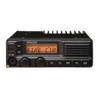
VHF FM TRANSCEIVER
TK-780
SERVICE MANUAL
GENERAL ................................................................. 2
OPERATING FEATURES ......................................... 3
REALIGNMENT...................................................... 16
INSTALLATION...................................................... 19
CIRCUIT DESCRIPTION ......................................... 26
SEMICONDUCTOR DATA ..................................... 31
DESCRIPTION OF COMPONENTS ....................... 32
PARTS LIST ............................................................ 34
EXPLODED VIEW .................................................. 43
PACKING ................................................................ 44
ADJUSTMENT ....................................................... 45
PC BOARD VIEWS
PLL/VCO (X58-4712-70) ................................... 54
SUB UNIT (X58-4850-10) : E3 .......................... 54
TX-RX UNIT (X57-6142-XX) (A/2) ................... 55
TX-RX UNIT (X57-6142-XX) (B/2).................... 61
SCHEMATIC DIAGRAM ........................................ 65
BLOCK DIAGRAM.................................................. 73
LEVEL DIAGRAM ................................................... 76
TERMINAL FUNCTION ......................................... 78
SPECIFICATIONS................................................... 79
CONTENTS
REVISED E·E3 versions
Cabinet (Upper)
(A01-2165-23)
Panel assy
(A62-0642-03)
Key top
(K29-9105-02)
This Service Manual was revised based on the service
manual as per parts No. B51-8523-00, in order to include
new variants with the following destination codes : E3.