Do you have a question about the Kenwood TM-732A and is the answer not in the manual?
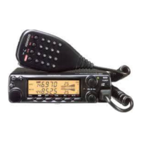
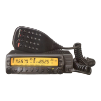
Provides an overview of the TM-732A/E transceiver's features and design.
Lists the key features and capabilities of the dual-band transceiver.
Lists the standard accessories included with the transceiver.
Explains how the transceiver handles frequency reception and synthesis.
Details the transmit circuit for the 144MHz band.
Details the transmit circuit for the 430MHz band.
Explains the receive circuit for the 144MHz band.
Explains the receive circuit for the 430MHz band.
Details the sub-receive circuit for the 144MHz band.
Details the sub-receive circuit for the 430MHz band.
Explains the operation of the squelch circuit.
Describes the shift register circuit for the 144MHz band.
Explains the voltage output variation of the SQL circuit.
Outlines the AF signal path from detection to audio output.
Explains the functions of the digital control unit.
Describes how audio signals are routed to different speakers.
Explains the DTMF encoding and decoding functions.
Describes how analog signals are switched.
Explains the power-on reset and backup operation circuits.
Details the circuit for amplifying microphone signals.
Outlines the functions of the panel unit microprocessor.
Explains the LCD display driving circuit.
Explains the PLL synthesizer for the 430MHz band.
Explains the PLL synthesizer for the 144MHz band.
Lists the specifications for the transceiver's I/O ports.
Explains the PLL IC's operational modes.
Details VHF squelch shift register functions.
Provides equivalent circuit and electrical characteristics of the final module.
Provides equivalent circuit and electrical characteristics of another final module.
Shows the circuit diagram for the drive HIC KCB11.
Shows the circuit diagram for the 80RF HIC KCB13.
Shows the circuit diagram for the drive HIC KCB14.
Shows the circuit diagram for the AF IF HIC KCD05.
Shows the circuit diagram for the FM IF HIC KCD04.
Lists components (Q1-Q14) and their functions for the TX-RX unit.
Lists components Q214-Q218 and their functions.
Lists functions for various ICs and an amplifier.
Details the functions of IC8 (Shift register) and IC9 (PLL).
Details functions for DTMF encoder/decoder and microprocessor.
Lists functions for multiplexer, electronic VR, and AVR.
Lists functions for various diodes.
Explains the wired cloning procedure.
Explains the DTMF cloning procedure.
Details capacitor codes, voltage ratings, and dimensions.
Details resistor codes and wattage ratings.
Covers items like cabinets, panels, cables, and connectors.
Covers cushions, protection items, cartons, and fuses.
Covers knobs, switches, and microphone elements.
Lists inductors and various connectors.
Lists resistors and diodes.
Lists integrated circuits and transistors.
Lists the necessary test equipment for adjustments.
Outlines preparation steps for adjustments.
Lists frequencies for different bands and destinations.
Describes the procedure for resetting settings and memory.
Details voltage checks for VHF and UHF bands.
Specifies transmission frequencies and SSG settings.
Explains sensitivity adjustments for VHF and UHF bands.
Describes how to adjust for high-level input signal-to-noise ratio.
Details distortion adjustments for VHF and UHF bands.
Explains S-meter adjustment procedures.
Describes squelch adjustment steps.
Continues squelch adjustment steps for different bands and SSG levels.
Describes checking external speaker switching.
Details power output adjustments for HI, MID, and LOW settings.
Continues power output adjustments for different bands and settings.
Explains DC voltage adjustments and checks.
Describes tone generation adjustments.
Details DTSS adjustment steps.
Explains how to check for spurious oscillations.
Describes CTCSS adjustments.
Shows the physical locations of adjustment points on the boards.
Lists terminal functions for the TX-RX unit.
Details terminal functions for connector CN1.
Details terminal functions for connector CN2.
Shows the component layout of the 144MHz TX-RX unit.
Shows the foil layout of the 144MHz TX-RX unit.
Provides the circuit diagram for the 144MHz TX-RX unit.
Continues the circuit diagram for the 144MHz TX-RX unit.
Continues the circuit diagram for the 144MHz TX-RX unit.
Continues the circuit diagram for the 144MHz TX-RX unit.
Continues the circuit diagram for the 144MHz TX-RX unit.
Shows the component layout of the 430MHz TX-RX unit.
Shows the foil layout of the 430MHz TX-RX unit.
Details the control unit circuit diagram connections.
Shows the DTMF decoder circuit.
Details the multi-plexor circuits.
Shows the component layout of the control unit.
Shows the foil layout of the control unit.
Shows the component layout of the volume unit.
Shows the component layout of the LCD assembly.
Provides connections between units and the control unit.
Shows connections to the 144MHz TX-RX unit.
Shows the schematic diagram for the LCD assembly.
Details the components connected to the LCD driver.
Shows the block diagram of the display unit.
Provides a block diagram of the control unit.
Shows the block diagram for the 144MHz TX-RX unit.
Continues the block diagram for the 144MHz TX-RX unit.
Illustrates signal levels in the transmitter path.
Illustrates signal levels in the receiver path.
Shows the external appearance of the MC-45 microphone.
Lists the parts for the MC-45 microphone.
Provides the schematic diagram for the MC-45 microphone.
Shows the external appearance of the MC-45DM microphone.
Lists the parts for the MC-45DM microphone.
Provides the schematic diagram for the MC-45DM microphone.
Shows the external view of the PG-4K panel separation kit.
Details the dimensions and parts of the PG-4K panel.
Describes the PG-4K panel cable.
Shows the external appearance of the TSU-7 unit.
Lists the parts for the TSU-7 unit.
Shows the PC board layout of the TSU-7 unit.
Provides the circuit diagram for the TSU-7 unit.
Lists general specifications like frequency range and mode.
Details transmitter specifications like output power and modulation.
Details receiver specifications like sensitivity and selectivity.
| Mode | FM |
|---|---|
| Supply | 13.8V DC |
| Antenna Impedance | 50 Ohms |
| Weight | 1.2 kg |
| Frequency Range | 144-148 MHz, 430-450 MHz |
| Channel Step | 5, 10 kHz |
| Power Supply | 13.8V DC |
| Channels | 200 (100 VHF, 100 UHF) |