Do you have a question about the Kenwood VFO-120 and is the answer not in the manual?
Details the AGC-type speech processor and its effect on ALC time constant.
Describes the single conversion PLL frequency system and its basic configuration.
Explains the PLL circuit construction and frequency operation.
Describes the CAR oscillator and its frequency variation.
Details the VFO oscillator circuit and added indicators.
Explains the VFO frequency counting system and its components.
Explains the VSWR protection and temperature protection circuits.
Details the ALC protection, fan drive, AVR, and filter circuits.
Describes temperature protection and fan drive circuits for the final unit.
Shows the component layout for the processor unit.
Shows component layout for the IF unit (S/V types).
Component layout view for the PLL unit.
Component layout view for the counter unit.
Component layout view for the RF unit.
Component layout view for the VFO unit.
Component layout view for the CAR unit.
Component layout for Switch Units A and B.
Component layout view for the AF-GEN unit.
Component layout view for the Relay unit.
Component layout for Filter Units S and V types.
Component layout for Final Units V and S types.
Schematic diagram for the IF unit.
Schematic diagram for the PLL unit.
Schematic diagram for the Counter unit.
General parts list for the TS-130S/V.
Detailed parts lists for various units like switches, RF, IF, AF-GEN, CAR, PLL.
Exploded view for disassembling the Final Unit (S type).
Exploded view for disassembling the Final Unit (V type).
Overview of adjustment procedures and classification.
List of essential test equipment for adjustments.
Initial control settings required before adjustments.
Adjustment procedure for the RIT control.
Adjustment steps for the Voltage Controlled Oscillator.
Adjustment of transmit and receive bandpass filters.
Adjustment of PLL bandpass filters A, B, and C.
Adjustments for IF amplifier stages and traps.
Adjustment procedure for the Noise Blanker circuit.
Adjusting carrier balance and S meter levels.
Adjustment of base current for S and V types.
Adjusting carrier level and ALC settings.
Adjustments for protection circuits and TX spurious emissions.
Adjusting SSB carrier point and suppression.
Adjustments for speech processor and side tone.
Diagrams for test equipment setup for alignment.
Alignment points indicated on PC board layouts.
Diagrams for test equipment setup for alignment.
External view of the AT-130 antenna coupler.
Technical specifications for the AT-130.
Schematic diagram for the AT-130.
Block diagram illustrating system interconnections.
Parts list for the AT-130 antenna coupler.
Technical specifications for the VFO-120.
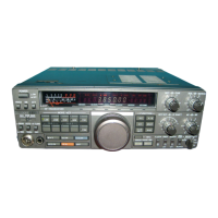
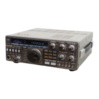
External view of the VFO-120.
Block diagram of the transceiver system.
Parts list and schematic for the VFO unit.
Parts list and schematic for the Switch unit.
Parts list and schematic for the VFO Assembly unit.
Parts list and schematic for the Indicator unit.
| Brand | Kenwood |
|---|---|
| Model | VFO-120 |
| Category | Transceiver |
| Language | English |