Do you have a question about the Kenwood X-45 and is the answer not in the manual?
Warning about using the amplifier's power supply or a provisional source for repair.
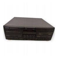
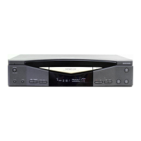
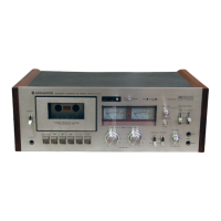
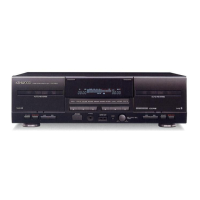
Identifies and describes the function of front panel keys and displays.
Details the multi-display, peak level indicator, and transport mode indicators.
Explains Fade-out, Erase, Cross-fade, and Normal edit recording.
Details AI EDIT, MULTI EDIT, and double-speed recording operations.
Details the functions of integrated circuits (ICs) and transistors within the unit.
Explains system functions, key operations, modes, and the key matrix.
Covers synchronized recording, audio processing IC, and serial data communication.
Details test modes, microprocessor, expansion IC, and operation timing diagrams.
Diagrams showing mechanism parts layout and transmission of rotation.
Step-by-step descriptions of mechanism actions for various playback and recording modes.
Details azimuth, tape speed, and playback level adjustments.
Describes the procedure for adjusting the bias current for optimal recording.
Diagram showing the exploded view of the cassette mechanism unit.
Diagram showing the exploded view of the main cassette deck unit.
Lists parts for Section No. 7, including part numbers and descriptions.
| Brand | Kenwood |
|---|---|
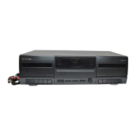
| Model | X-45 |
| Category | Cassette Player |
| Language | English |