Do you have a question about the Kenwood X-85 and is the answer not in the manual?
General safety advice before repairing the cassette deck.
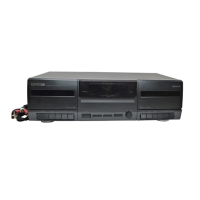
Illustration and labels for the rear panel connectors and ports.
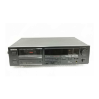
Description of buttons, keys, and displays on the front panel.
Instructions and diagrams for taking apart the cassette deck.
Explanation of various recording techniques and their functions.
Visual representation of the cassette deck's main functional blocks.
Details on ICs, transistors, and their functions within the circuit.
Synchronous recording, IC details, serial data, test modes, and pinouts.
Visual representation of signal timing for various operations.
Diagram illustrating the wiring connections between units and mechanisms.
Diagram showing component placement on the printed circuit board.
Detailed electrical schematics for the cassette deck's circuits.
Visual breakdowns of the mechanism and overall unit for assembly/disassembly.
Comprehensive list of all parts with their numbers, descriptions, and locations.
Detailed specifications for performance, power, and dimensions.
| Brand | Kenwood |
|---|---|
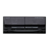
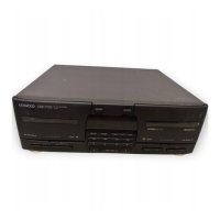
| Model | X-85 |
| Category | Cassette Player |
| Language | English |