EasyManua.ls Logo

Kenwood X-E5 User Manual

Kenwood X-E5
54 pages
To Next Page IconTo Next Page
Page #1 background imageLoading...
Page #1 background image
|
STEREO
DOUBLE
AUTO
REVERSE
CASSETTE
DECK
vac:
KENWOOD
SERVICE
MANUAL
|
|
|
|
(U
D-502)
|
©
1994-8
PRINTED
IN
KOREA
|
B51-4944-00(
K)
2461
Cassette
lid
(A)
Metallic
cabinet
Front
glass
(A)
Front
glass
(B)
Cassette
lid
(B)
(453-1806-02)
{A01-3144-11)
(B10-2032-02)
(B10-2033-02)
{A53-1807-02)
j
|
|
|
|
eee
|
|
i
|
|
i
|
|
|
|
Knob
(EJECT)
Panel
(FRONT)
Front
glass
(CD)
Panel
(CD
TRAY)
Knob
(OPEN/CLOSE)
Knob
(EJECT)
(K29-5983-04)
(A60-0596-11)
(B10-2034-13)
(A29-0371-03)
(K29-5947-04)
(K29-5984-04)
PRECAUTIONS
FOR
REPAIR
*
Since
the
power
for
this
device
is
supplied
by
the
receiver/multi-command
(A-E5),
the
latter
or
the
jig
(PS-93UA
or
PS-94UA)
is
required
for
repair
of
the
former.
*
Since
this
device
does
not
have
operation
keys,
we
recommend
to
use
A-E5.
If
this
device
is
set
to
the
test
mode,
the
jig
can
be
used
*
For
the
operation
of
the
cassette
mechanism,
see
Service
Manual
(B51-4869-00)
of
RXD-C3/C3L.
Question and Answer IconNeed help?

Do you have a question about the Kenwood X-E5 and is the answer not in the manual?

Kenwood X-E5 Specifications

General IconGeneral
BrandKenwood
ModelX-E5
CategoryCassette Player
LanguageEnglish

Summary

Precautions and Accessories

Precautions for Repair

Essential safety and operational guidelines before commencing repairs.

Included Accessories

Lists system configurations and all included accessories for the unit.

Controls and Operation

Cassette and CD Player Controls

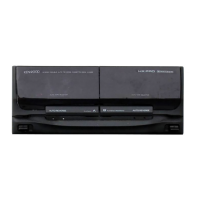
Identifies and describes operational buttons and indicators on cassette and CD units.

Remote Control Unit Key Functions

Details the functions and operation of each key on the remote control unit.

System Diagrams and Circuitry

Block Diagrams (CD and Deck)

Illustrates functional blocks and signal flow for CD player and cassette deck sections.

Circuit Description (Microcomputers, Pins, Features)

Details circuitry, pin functions, and features of CD, Deck, and Cassette mechanisms.

Test Mode Procedures

Initial Settings, Port Configurations, and Test Types

Describes initial settings, port configurations for test modes, and test types.

Test 1 Operation, Key Assignments, and LED Indicators

Outlines Test 1 steps, keys, and explains LED indicator meanings.

REC Operations, Tape Speed, and Level Adjustments

Details REC functions, tape speed adjustment, and volume/CCRS level checks.

Adjustment Procedures

Preparation, Connection Diagrams, and CD Player Adjustment

Covers adjustment preparation, diagrams, and initial CD player settings.

Cassette Deck Adjustment Procedures

Details preparation, tape speed, Test 1, and sync modes for cassette deck adjustments.

Manual and Automatic Adjustment Modes

Explains manual/automatic adjustment processes, results, and status codes.

Diagrams and Parts

Wiring Diagram

Illustrates the electrical connections between components and units.

PC Board Component View

Shows the physical layout of components on the main circuit boards.

Schematic Diagrams

Provides detailed electrical circuit schematics for the unit.

Exploded Views (CD, Cassette, Unit)

Shows part breakdowns for CD mechanism, cassette mechanism, and the main unit.

Parts List

Lists all part numbers, descriptions, and specifications for the unit.

Specifications

Related product manuals