EN-UK
Installation
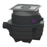
The inlet can be mounted at various positions on the system
tank:
Item Connection
2 DN 100
6 DN 100
7 DN 80
8 DN 50 or DN 100
9 Scoring surface, maximal DN 100.
Ensure that backflowing wastewater does not get
into the inlet pipe.
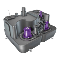
Mounting the inlet
Modify the level sensor installation (position) if necessary.
Mount the inlet on the system tank.
Mounting the outlet
Connect the pressure pipe to the connection (7).
5.4 Connecting the ventilation pipe
Saw off the socket for the ventilation pipe (1) at the indi-
cated cutting edge.
Connect the ventilation pipe to the ventilation connection
(1)
Route a separate ventilation pipe to above the roof level
as stipulated in EN 12056-4.
5.5 Planning a connection for manual diaphragm pump
Provide a connection for a manual diaphragm pump at
the connection socket (1) (DN 40), if required.
28 / 112 Lifting station/Installation and operating instructions 010-974