EasyManua.ls Logo

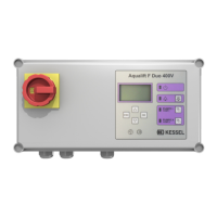
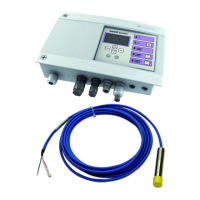
Kessel Aqualift F Duo 400V User Manual

Kessel Aqualift F Duo 400V
204 pages
Go to English
To Next Page IconTo Next Page
Page #1 background imageLoading...
Page #1 background image
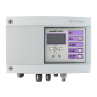
Aqualift Comfort
400V Mono/Duo
Einbau- und Betriebsanleitung
Aqualift Comfort
400V Mono/Duo
Einbau- und Betriebsanleitung
Aqualift Comfort
400V Mono/Duo
Einbau- und Betriebsanleitung
DE Einbau- und Betriebsanleitung..........................2
EN Installation and operating manual...................34
FR Instructions de pose et d’utilisation.................66
IT Istruzioni per l’installazione e l’uso............... 101
NL Inbouw- en montagehandleiding...................135
PL Instrukcja zabudowy i obsługi.......................168
2020/05 010-532_07

Other manuals for Kessel Aqualift F Duo 400V

Questions and Answers:

Kessel Aqualift F Duo 400V Specifications

General IconGeneral
Number of pressure pipes2
Pump typeSubmersible pump
Operating voltage400V
Mains frequency50 Hz
Protection classIP 68
Protection class of the control unitIP 54
Max. medium temperature (continuous operation)40 °C
Short-term max. medium temperature60 °C
Impeller typeVortex impeller
Free passage50 mm
Inlet nominal size (DN)100
Number of inlets2
Tank volume60 L
Switching volume30 L
Product designationAqualift F Duo
Installation typeFloor-standing
ApplicationWastewater
Type of currentAC
Delivery mediumWastewater
Inlet height180 mm
MaterialPolyethylene
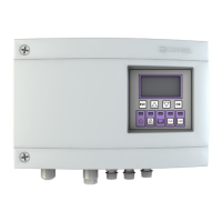
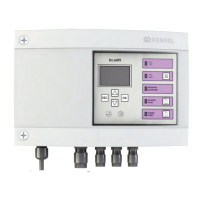
TypeControl Unit

Summary

Notes on this Manual

Safety

Personnel - Qualification

Details operator qualifications, risk assessment, and safety training requirements.

Intended Use

Defines the control unit's purpose and specifies it's not for EX zones.

ATEX Safety Notes

Explains ATEX marking and safety measures for explosive zones.

Technical Data

ATEX Design Information

Provides additional technical specifications related to ATEX compliance.

Installation

Control Unit Installation

Step-by-step guide for installing the control unit housing and mounting.

ATEX Requirement Assurance

Outlines electrical installation requirements for ATEX compliance.

Mains Cable Connection

Instructions for connecting the 400V mains cable to the control unit.

Pump Connection

Details on connecting pumps, including motor protection switch settings.

Sensor and Control Connection

Covers connecting various sensors (pressure, float, level) and control elements.

Further Connection Options

Information on additional connections like GSM modems and USB routing.

Connection Diagrams

Visual diagrams illustrating wiring for Mono and Duo systems.

Initial Commissioning

Power On/Off

Basic steps for switching the control unit on and off.

Initialisation Process

Guides through essential setup steps like language, date, and system configuration.

Troubleshooting

Battery Error

Addresses issues related to battery status or voltage.

Maintenance Date Error

Alerts users to issues with maintenance scheduling.

Undercurrent Error

Indicates low power consumption or cable issues for the pump.

Overcurrent Error

Signifies excessive power consumption or pump blockage.

Relay Error

Relates to the power contactor not switching correctly.

Power Outage

Covers issues related to power supply failures or fuse trips.

Temperature Error 1a/2a

Addresses self-resetting temperature monitoring faults.

Temperature Error 1b/2b

Addresses non-self-resetting temperature monitoring faults.

Level Error

Indicates incorrect sensor wiring or configuration issues.

Phase Failure

Signifies a loss of one or more power phases.

Rotating Field Error

Relates to incorrect phase rotation in the mains connection.

Motor Protection Error

Covers issues with the motor protection switch or pump blockage.

Pressure Loss

Indicates leaks in the pressure system or at fittings.

Relay Operating Cycles

Warns about exceeding the maximum number of operating cycles.

Max. Run Time Error

Indicates the pump is running for excessively long periods.

Max. Run Occur Error

Indicates the pump is running too frequently in a short time.

Overview of Configuration Menu

0 System Info

Displays system status, sensors, values, events, and errors.

1 Information

Shows operating data like voltage, measured values, and logbook.

1.1 Hours of Operation

Displays total and pump-specific running times and starts.

1.2 Log Book

Records system events and operational history.

1.3 Control Type

Indicates the type of control system used.

1.4 Maintenance Date

Displays last and next maintenance dates.

1.5 Current Measured Values

Shows real-time values for mains voltage, power, battery, and filling level.

1.6 Parameter

Allows adjustment of various system parameters like sensor height and levels.

1.6.10 Max. Run Time

Sets the maximum allowed running time for the pump.

1.6.11 Max. Run Occur

Configures the maximum frequency of pump starts within a period.

1.6.12 Min. Current

Sets the minimum current threshold for pump operation.

1.6.13 Max. Current

Sets the maximum current threshold for pump operation.

1.6.16 S1/S3 Operation

Configures the operating mode (S1 or S3).

Maintenance

2.1 Automatic Operation

Controls the automatic operation mode of the system.

2.2 SDS

Settings related to the SDS (System Diagnostic Service).

2.3 Maintenance Date

Sets and displays maintenance dates.

2.4 Maintenance Done

Records when maintenance tasks have been completed.

2.5 Maintenance Interval

Defines the frequency for scheduled maintenance.

2.6 Calibration

Procedures for calibrating the system components.

Settings

3.1 Parameter

Allows adjustment of various system parameters.

3.2 Profile Memory

Manages saving and loading of system configurations.

3.3 Date/Time

Sets the current date and time for the system.

3.4 System Configuration

Configures the specific system type and model.

3.8 Sensor Configuration

Configures the type and settings of connected sensors.

3.9 Communication

Settings for communication parameters like station name and modem type.

3.10 Language

Selects the display language for the control unit.

3.11 Reset

Options for resetting the control unit to factory settings.

3.12 Expert Mode

Accesses advanced settings and parameters.

0 Data Exchange

Options for data read-out, software updates, and parameter import.

Related product manuals