
K
Karen PerezAug 18, 2025
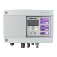
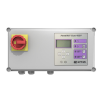
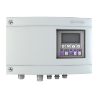
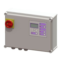
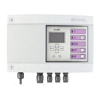
What to do if Kessel Aqualift Comfort 230V Duo Control Unit experiences a power outage?
- KKatherine HurleyAug 18, 2025
A power outage in the Kessel Control Unit can occur due to a failed power supply, a blown unit fuse, or an interrupted mains supply cable. To resolve this, first check the fuse. Then, inspect the mains supply cable. Note that in case of intentional shutdown, the control unit should be shut down properly.