19
EN
3 - PRELIMINARY CHECKS
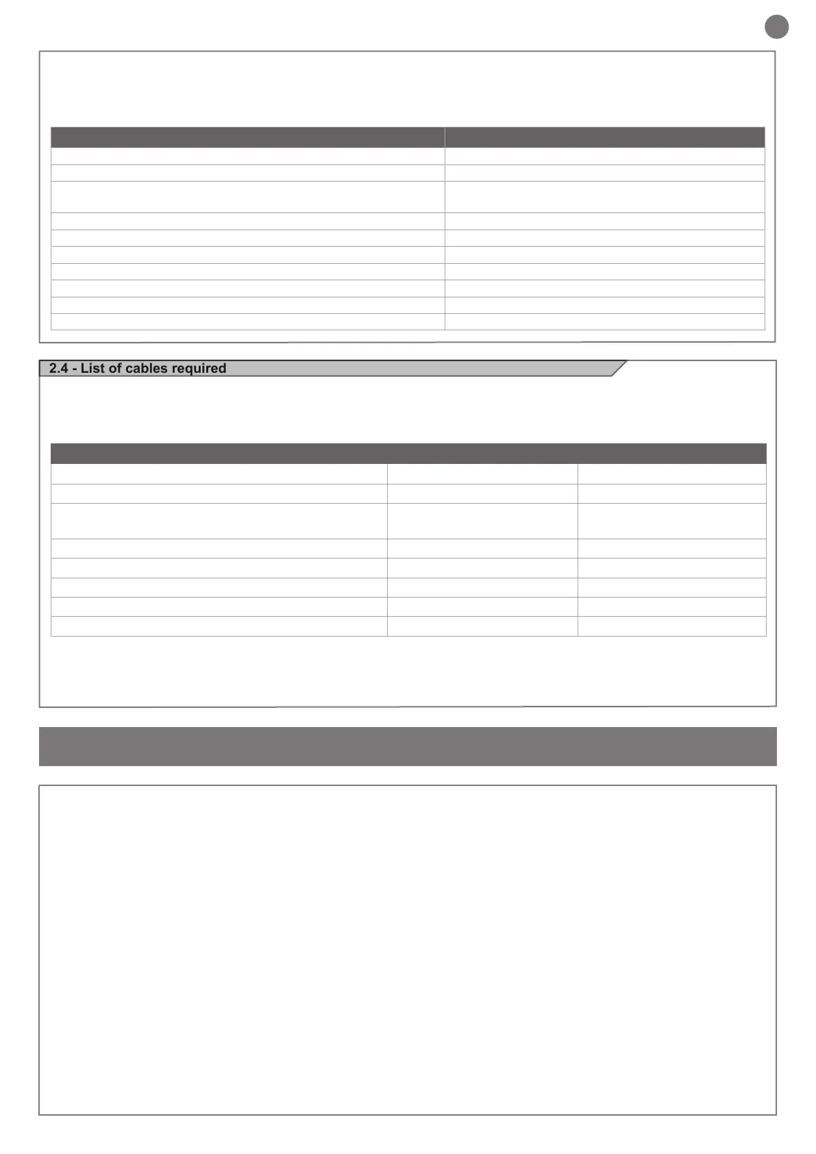
2.4 - List of cables required
The cables required for connection of the various devices in a stan-
dard system are listed in the cables list table.
Before installing the product, perform the following checks and in-
spections:
check that the gate, the door or the barrier is suitable for automation;
the weight and size of the gate or door and the balance of the barrier
boom must be within the operating limits specied for the automa-
tion system in which the product is installed;
heck that the gate or door has rm, effective mechanical safety
stops;
make sure that the product xing zone is not subject to ooding;
high acidity or salinity or nearby heat sources might cause the pro-
duct to malfunction;
in case of extreme weather conditions (e.g. snow, ice, wide tempe-
rature variations or high temperatures), friction may increase, cau-
sing a corresponding rise in the force needed to operate the system;
the starting torque may therefore exceed that required in normal
conditions;
check that when operated by hand the gate, the door or the barrier
moves smoothly without any areas of greater friction or derailment
risk;
check that the gate, door or the barrier is well balanced and will the-
refore remain stationery when released in any position;
check that the electricity supply line to which the product is to be
connected is suitably earthed and protected by an overload and dif-
ferential safety breaker device;
he system power supply line must include a circuit breaker device
with a contact gap allowing complete disconnection in the condi-
tions specied by class III overvoltage;
ensure that all the material used for installation complies with the
relevant regulatory standards.
The cables used must be suitable for the type of installation; for
example, an H03VV-F type cable is recommended for indoor appli-
cations, while H07RN-F is suitable for outdoor applications.
- Power supply with protection against short-circuits inside the con-
trol unit, on motors and on the connected accessories.
- Obstacle detection.
- Automatic learning of working times.
- Safety device deactivation by means of dip switches: there is no
need to bridge the terminals of safety devices which are not instal-
led - the function is simply disabled by means of a dip switch.
* If the power supply cable is more than 20 m long, it must be of larger gauge (3x2.5mm2) and a safety grounding system must be installed
near the automation unit.
TECHNICAL SPECIFICATIONS:
Power supply (L-N) 230 Vac (+10% - 15%) 50-60 Hz
Max motor load 150 W
Output for Vac accessories power/device test power Vdc
24 Vac without regulation 200 mA / 24 Vdc without regu-
lation 250 mA
Courtesy light output 24 Vdc 25 W
Flashing light output 24 Vdc 25 W
Pause time Adjustable 0-900 sec.
Operating temperature -20 °C + 55 °C
230 Vac power supply line fuses 1.6 A slow-acting
Max. number of transmitters storage FIX CODE 150 transmitters
Max. number of transmitters storage ROLLING CODE 150 transmitters
ELECTRIC CABLE TECHNICAL SPECIFICATIONS:
Connection cable maximum allowable limit
Control unit power supply line 1 x cable 3 x 1,5 mm
2
20 m *
Flashing light, courtesy light
Antenna
3 x 0,5 mm
2
**
1 x cable type RG58
20 m
20 m (advised < 5 m)
Electric lock 1 x cable 2 x 1 mm
2
10 m
Transmitter photocells 1 x cable 2 x 0,5 mm
2
20 m
Receiver photocells 1 x cable 4 x 0,5 mm
2
20 m
Sensitive edge 1 x cable 2 x 0,5 mm
2
20 m
Key-switch 1 x cable 4 x 0,5 mm
2
** 20 m

 Loading...


