20
EN
4 - PRODUCT INSTALLATION
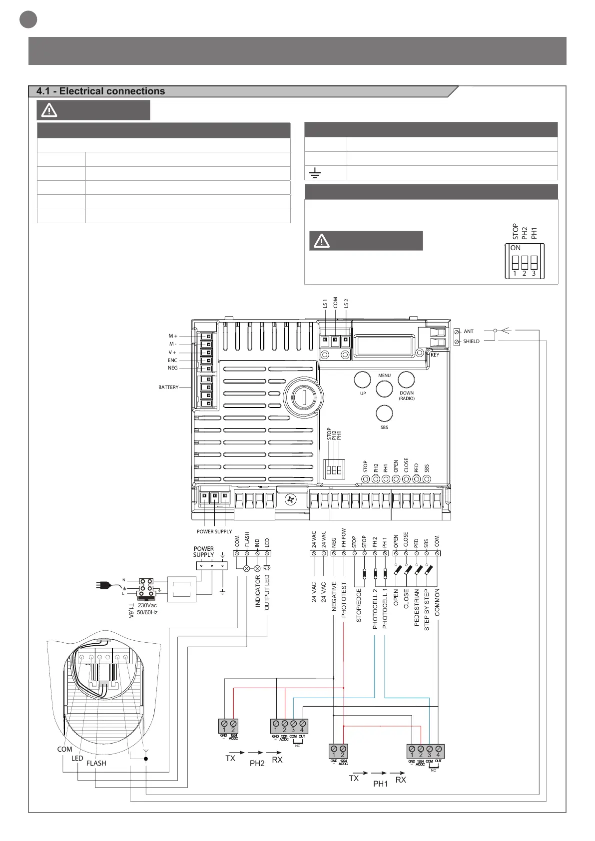
4.1 - Electrical connections
Before making the connections, ensure that the control unit is not powered up
MOTOR CONNECTOR
Power supply connection terminal board
M + Power supply motor
M - Power supply motor
V + Power supply encoder
ENC Encoder signal
NEG Maximum encoder power supply
POWER SUPPLY CONNECTOR
L Power supply live 230 Vac (120 Vac) 50-60 Hz
N Power supply neutral 230 Vac (120 Vac) 50-60 Hz
Earth
DIP SWITCH
Set on “ON” to disable inputs STOP, PH1, PH2
Eliminates the need to bridge the terminal board inputs.
with the dip switch ON,
the safety devices are disabled
WARNING
WARNING
NEG
PH-POW
STOP
STOP
PH 2
COM
FLASH
IND
LED
24 VAC
24 VAC
PH 1
OPEN
CLOSE
SBS
PED
COM
PHOTOTEST
OUTPUT LED
OPEN
PHOTOCELL 1
PHOTOCELL 2
CLOSE
PEDESTRIAN
STEP BY STEP
COMMON
STOP/EDGE
INDICATOR
NEGATIVE
24 VAC
24 VAC
2
3
4
1
1
2
TX
RX
NC
PH2
2
3
4
1
1
2
TX
RX
PH1
GND
_
12/24
AC/DC
GND
_
12/24
AC/DC
COM
OUT
GND
_
12/24
AC/DC
GND
_
12/24
AC/DC
COM
OUT
NC
POWER
POWER SUPPLY
SUPPLY
N
T1,6A
L
230Vac
50/60Hz
COM
LED
FLASH
STOP
STOP
PH2
PH1
OPEN
CLOSE
PED
SBS
PH2
PH1
SHIELD
UP
MENU
SBS
DOWN
(RADIO)
ANT
NEG
ENC
V +
M -
M +
BATTERY
LS 1
LS 2
KEY
COM

 Loading...


