18
EN
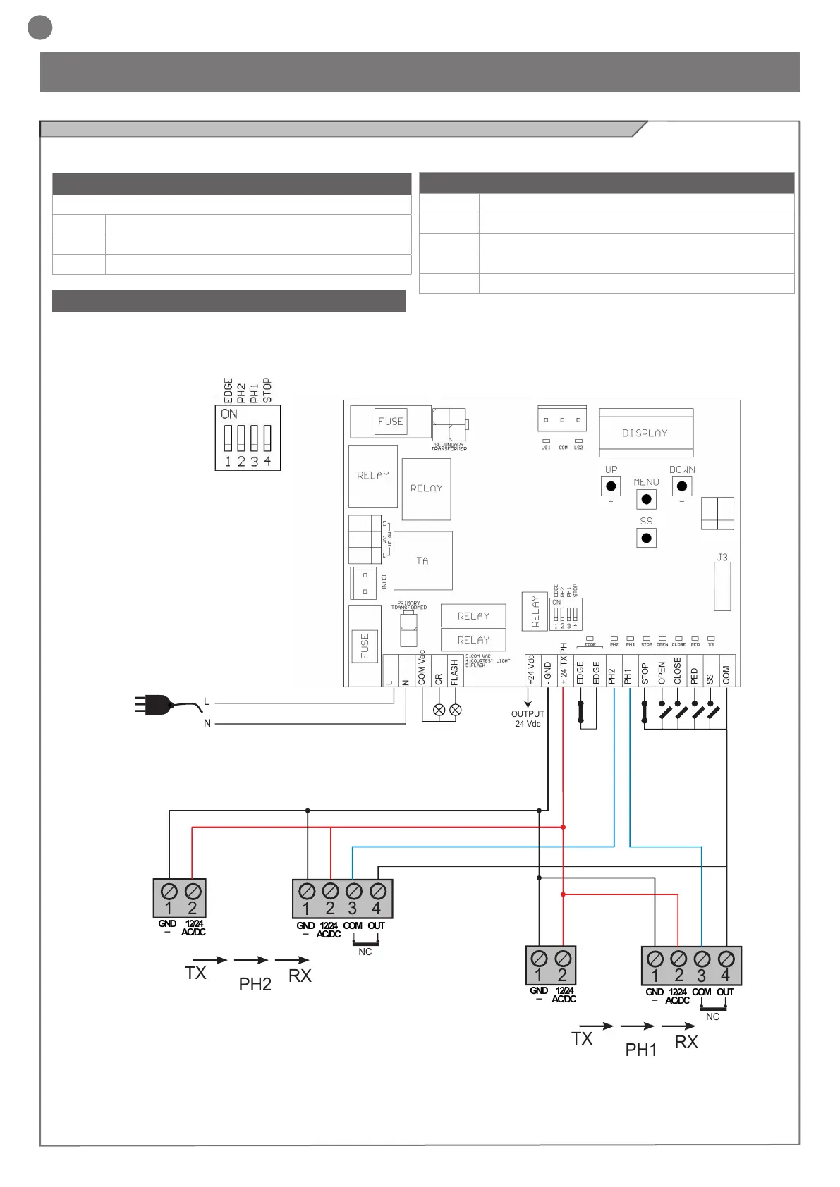
4 - PRODUCT INSTALLATION
MOTOR CONNECTOR
Power supply connection terminal board
L1 Motor live
COM Motor common
L2 Motor live
POWER SUPPLY CONNECTOR
L Power supply live 230 Vac (120 Vac) 50-60 Hz
N Power supply neutral 230 Vac (120 Vac) 50-60 Hz
COM Vac Common of the “CR” and “FLASH” outputs
CR Courtesy light, 230 Vac (120 Vac) 100 W
FLASH Flashing light, 230 Vac (120 Vac) 40 W
DIP SWITCH
Set on “ON” to disable inputs EDGE, PH2, PH1, STOP.
Eliminates the need to bridge the terminal board inputs.
WARNING - with the dip switch ON, the safety
devices are disabled
4.1 - Electrical connections
WARNING - Before making the connections, ensure that the control unit is not powered up.
+24 Vdc
- GND
+ 24 TX PH
EDGE
EDGE
PH2
PH1
STOP
OPEN
CLOSE
PED
SS
COM
L
N
COM Vac
CR
FLASH
OUTPUT
24 Vdc
2
3
4
1
1
2
TX
RX
NC
PH2
2
3
4
1
1
2
TX
RX
PH1
N
L
GND
_
12/24
AC/DC
GND
_
12/24
AC/DC
COM
OUT
GND
_
12/24
AC/DC
GND
_
12/24
AC/DC
COM
OUT
NC