Installation Note N9030-90077 27
Option BBA, Analog Baseband I/Q Inputs Upgrade Kit
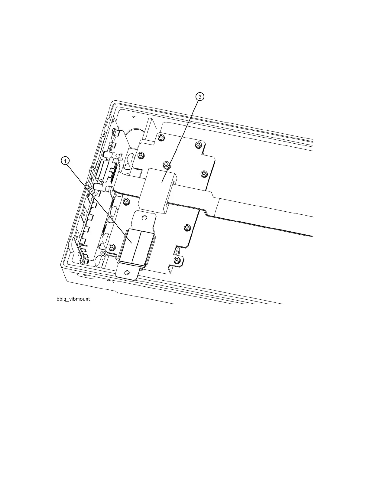
12.Refer to Figure 20. Cut the Vibration Mount 0460-2725 (3 ) supplied in the kit into four pieces
with scissors or a knife to fit the Core Bracket, Top (2) N9020-00071 and the Core Bracket,
Bottom (4) N9020-00072.
Figure 20 Vibration Mount Installation
13.Position the Core Bracket, Bottom with the vibration mount facing upward into the opening of
the display shield.
14.Position the ferrite core that is on the ribbon cable over the Core Bracket, Bottom.
15.Position the Core Bracket, Top over the ferrite core. Secure with four 0515-0372 screws (5).
Torque to 9 in-lbs.
16.Plug the ribbon cable W1 into the motherboard.
17.Refer to Figure 2. Carefully install the front panel assembly making sure that the flex cable is
not pinched. Also, align the BBIQ Interface Board properly so the components do not become
damaged by the fan bracket sheet metal.
18.Secure the front panel with screws 0515-2032 in 8 places, 4 on each side. Torque to 9 in-lbs.

 Loading...