Operation and Service Guide 1
Keysight E4412A and E4413A Operating and Service Guide 31
Procedure
1 Turn on the signal generator and power meter (with the reference sensor
connected). Connect the DUT to channel A of he power meter (E4416/7A), and
channel B of the reference sensor (E4412A).
Allow them to warm up for approximately an hour.
2 Zero and calibrate both the DUT and reference sensor.
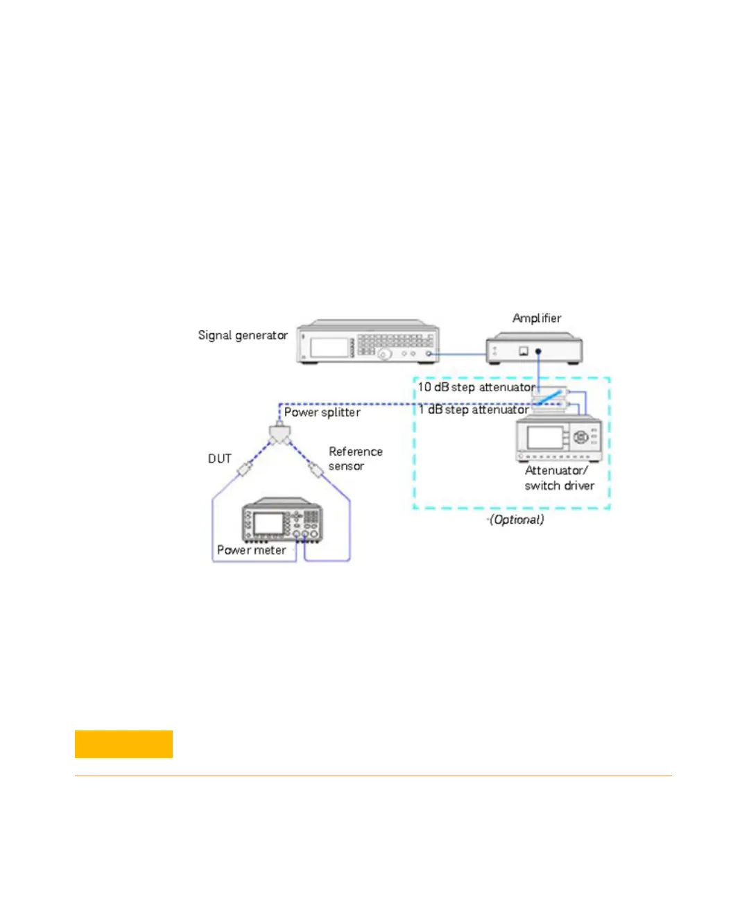
3 Connect the power splitter (11667B/11667C) to the RF output of the signal
generator (N5182A). The equipment setup is as shown in Figure 1-6.
Figure 1-6 Power linearity performance verification equipment setup
4 Set the continuous wave signal frequency of the signal generator, DUT, and
reference sensor to 50 MHz. Set the DUT to average-only mode.
5 Start tuning the signal generator and/or optionally tune the attenuator or
switch driver until the DUT (channel A) measures the power level as close as 0
dBm. Record the values as P
DUT
at 0 dBm and P
ref
at 0 dBm.
Do not exceed the maximum input power (27 dBm) of the power splitter to
avoid damage to the power splitter.