2
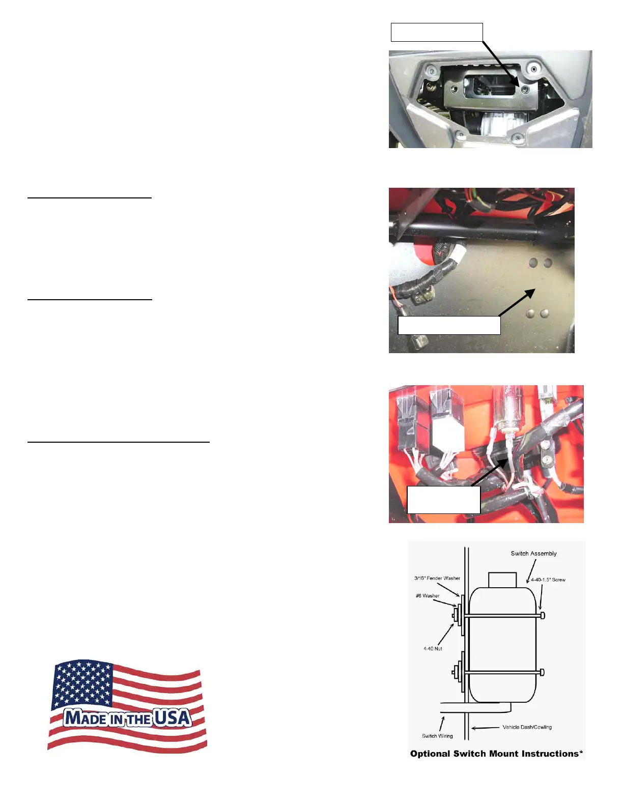
6. Assemble the Fairlead Bracket to the RZR Frame as
shown in Figure 5 and the exploded view above
usi
ng the 5/16” hardware supplie
d.
7. Assem
ble your Fairlead to th
e fairlead bracket
w
hile routing the cable thru. Attach your hook
.
8. Replace ha
rdware removed from
Step 2.
9. U
sing the instructions provided with your winch,
wire accordi
ngly.
CO
NTACTOR LOCATION
Contactor l
ocation is just above the passengers feet as
shown in Figure 6.
(Note: You may need to re-drill the
contactor mounting holes as there are a few contactors that
will not have the same mounting bolt pattern that is on your
RZR)
SWITCH IG
NITION WIRE
1. Crimp the red wire from the remote or switch
to the included Piggyback Quick Conn
ect.
2. Re
move the ORANGE electrical wire from
the
accessory outlet and connect it to the
piggybac
k electrical connector. Figure
7
3. Connect the
Piggyback connector to the
accessory outlet.
Mini-Rocker Switch Hardware Kit
This allows you to mount your usual handle bar mounted switch
to almost any desired location.
a. Remove handlebar mount hardware from th
e
switch
.
b. Locate desired mounting location
c. Mark and drill two switch holes through dash
using switch housing as a template
d. Drill a 3
rd
hole for the switch wiring.
e. Assemble per Figure 8
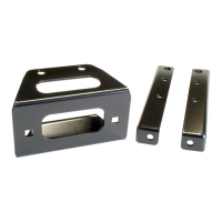
Fairlead Bracke
“Figure 5” Mount Fairlead Bracket
“Figure 8” Mini-Rocker Mounting
“Figure 6” Contactor Location
Contactor Location
“Figure 7” Switch Ignition Wire
Orange Wire
Discover other winches on our website.