EasyManua.ls Logo

KFI 100660 - User Manual

KFI 100660
2 pages
Print Icon
To Next Page IconTo Next Page
Loading...
1
(A)
Remove Bolts
“Figure 1” Remove Cover and bolts
“Figure 3” Front of Mounting Angles
3/8” Hardware
Polaris RANGER RZR
Winch Mount
Winch Mount PART # 100660
Hardware Kit – HK-032, HK-031
Kit Components:
Qty Part Description
2……………. LH and RH Winch Mounting Angle
1……………. Winch Mount fairlead bracket
4……………. 5/16 x 3/4” Hex Head Flange Bolts
4……………. 5/16” SAE Flat Washers
4……………. 5/16” Nylock Nuts
4……………. 3/8” x 1” Hex Head Bolts
4……………. 3/8” SAE Flat Washers
2……………. 3/8” Lock Washers
2……………. 3/8” x 3/4” Shortneck Carriage Bolt
4……………. 3/8” Nylock Nut
2……………. Piggyback Quick-Connect
1……………. Hardware kit (Mini-Rocker Switch)
INSTALLATION INSTRUCTIONS:
1. Begin by removing the plastic cover (A) and
discardin
g as sh
own in Figure 1.
2. For ease of asse
mbly remove 4 bolts as shown i
n
Figure 1.
3. Place LH and RH
mounting angles into positio
n as
shown in Figur
e 2 and 3. Assemble using the
3/8”
hardware sup
plied as shown in the above explo
ded
view. (Note: Make su
re you route the cables a
nd
hoses as shown in Figure 2)
4. Connect the shorter 2 electrical wires to your winch.
(Not
e: Your winch manual may state the opposi
te, but
you will need to
connect the shorter wires to y
our
winch
)
5. Place your Winch into position as shown in the above
exploded vie
w and assemble using the hardwa
re that
was supplied wi
th your winch. (Note: If you are
installing a 2-hole mounted winch you will ne
ed to
first in
stall the optional not included Converte
r Mount
#100480 as shown in Figure 4)
Note: The cable must come off
of the bottom of the spool.
Some 2-Hole mounted winches
may have the motor on the
opposite side as shown.
3/8” Bolt and Lock Washer
“Figure 2” Rear of Mounting Angles
Route Cables and Hoses as Shown
“Figure 4”
Exploded View of a 2-Hole Mounted Winch
Mount #100480 (not included)
(A)
Mounting Angles
Question and Answer IconNeed help?

Do you have a question about the KFI 100660 and is the answer not in the manual?

Summary

Winch Mount Installation Guide

Installation Instructions

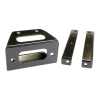
Step-by-step guide for physically mounting the winch and related hardware.

Winch Electrical Setup

Contactor Location

Specifies the mounting location for the winch contactor unit.

Switch Ignition Wiring

Explains how to wire the winch switch into the vehicle's ignition system.

Mini-Rocker Switch Mounting

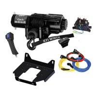
Instructions for installing a mini-rocker switch for winch operation.

Overview

This document provides installation instructions for a Polaris RANGER RZR Winch Mount, specifically Part # 100660, which includes Hardware Kit HK-032 and HK-031. The mount is designed to integrate a winch onto the Polaris RANGER RZR vehicle.

Function Description:

The Polaris RANGER RZR Winch Mount system facilitates the secure attachment of a winch to the RZR frame. It includes various components to ensure proper mounting, wiring, and operation of the winch. The system is designed to provide a robust mounting solution for winches, enabling their use for recovery or utility tasks. It also includes provisions for routing electrical cables and hoses, ensuring a clean and protected installation. An optional Mini-Rocker Switch Hardware Kit is provided to allow for flexible placement of the winch control switch, moving it from a standard handlebar mount to almost any desired location on the vehicle's dash or cowling.

Important Technical Specifications:

Kit Components (Winch Mount):

  • Winch Mounting Angles: Two (2) LH and RH angles for structural support.
  • Fairlead Bracket: One (1) bracket for the winch fairlead.
  • Fasteners (Mounting):
    • Four (4) 5/16 x 3/4" Hex Head Flange Bolts.
    • Four (4) 5/16" SAE Flat Washers.
    • Four (4) 5/16" Nylock Nuts.
  • Fasteners (Winch Assembly):
    • Four (4) 3/8" x 1" Hex Head Bolts.
    • Four (4) 3/8" SAE Flat Washers.
    • Two (2) 3/8" Lock Washers.
    • Two (2) 3/8" x 3/4" Shortneck Carriage Bolts.
    • Four (4) 3/8" Nylock Nuts.
  • Electrical Connectors:
    • Two (2) Piggyback Quick-Connects.
    • One (1) Hardware kit (Mini-Rocker Switch).

Mini-Rocker Switch Hardware Kit:

  • Fasteners:
    • One (1) 4-40-1.5" Screw.
    • One (1) 3/16" Fender Washer.
    • One (1) #6 Washer.
    • One (1) 4-40 Nut.

Usage Features:

Installation Process Overview:

  1. Initial Disassembly: Remove the plastic cover (A) and four existing bolts from the vehicle's front section.
  2. Mounting Angle Placement: Position the LH and RH mounting angles, ensuring proper routing of cables and hoses as depicted in Figure 2.
  3. Mounting Angle Assembly: Secure the mounting angles using the supplied 3/8" hardware.
  4. Winch Wiring (Initial): Connect the shorter two electrical wires to the winch. The manual notes that while a winch manual might suggest otherwise, the shorter wires should be connected to the winch.
  5. Winch Placement: Position the winch and assemble it using the supplied hardware.
    • Note for 2-Hole Winches: If installing a 2-hole mounted winch, the optional (not included) Converter Mount #100480 must be installed first.
    • Cable Routing: The winch cable must come off the bottom of the spool. Some 2-hole winches may have the motor on the opposite side.
  6. Fairlead Bracket Assembly: Attach the fairlead bracket to the RZR frame using the supplied 5/16" hardware.
  7. Fairlead and Cable Installation: Assemble the fairlead to its bracket, route the winch cable through it, and attach the hook.
  8. Reassembly: Replace the hardware removed in Step 2.
  9. Final Winch Wiring: Complete the winch wiring according to the instructions provided with the winch itself.

Contactor Location:

The contactor is typically located just above the passenger's feet. Users may need to re-drill mounting holes if their contactor's bolt pattern differs from the RZR's.

Switch Ignition Wire Connection:

  1. Crimp the red wire from the remote or switch to the included Piggyback Quick Connect.
  2. Remove the ORANGE electrical wire from the accessory outlet.
  3. Connect the ORANGE wire to the piggyback electrical connector.
  4. Connect the piggyback connector back to the accessory outlet.

Mini-Rocker Switch Mounting (Optional):

This kit allows for custom placement of the winch control switch.

  1. Remove the handlebar mount hardware from the switch.
  2. Identify the desired mounting location on the dash or cowling.
  3. Mark and drill two switch holes using the switch housing as a template.
  4. Drill a third hole for the switch wiring.
  5. Assemble the switch using the provided 4-40-1.5" screw, 3/16" fender washer, #6 washer, and 4-40 nut.

Maintenance Features:

The document does not explicitly detail maintenance features for the winch mount itself, as it is primarily an installation guide. However, proper routing of cables and hoses, as emphasized in the instructions, contributes to the longevity and reliability of the winch system by protecting components from damage. The use of durable fasteners (hex head flange bolts, SAE flat washers, nylock nuts, lock washers, carriage bolts) suggests a design intended for secure and lasting installation, minimizing the need for frequent re-tightening or replacement under normal operating conditions. The "Made in the USA" label implies a certain standard of manufacturing quality.

KFI 100660 Specifications

General IconGeneral
BrandKFI
Model100660
CategoryWinches
LanguageEnglish

Related product manuals