Note: Before installing make sure you have
the correct orientation for the switch with
the tab facing towards you.
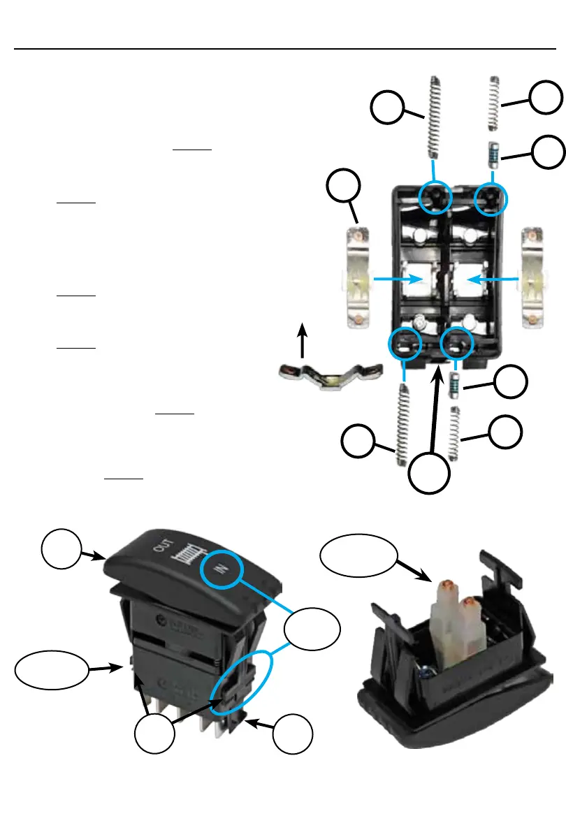
1. Insert the blue diodes (A) rst and small
spring (B) second into the designated hole
on each side shown in Figure 1.
2. Insert the two large springs (C) into the
designated holes on each side shown in
Figure 1.
3. Set the clips (D) Face up into the
designated location shown in Figure 1.
4. Set the white rocker plunger onto the post
in the top portion of the switch shown in
Figure 2.
5. Take the top portion of the switch and
set it on the bottom portion. Shown in
Figure 3.
6. Note: The “In” position is lined up with the
(Tab) on the one side of the switch so
you know how to attach it back together
correctly. Shown in Figure 3.
7. There is a clip on each side of the rocker
switch. Push the top portion of the switch
down and snap the clips into place.
Shown in Figure 3.
Plunger
Bottom
Clip
Tab
Top
Note
A
C
B
D
Face Up
Tab
A
C
B
Figure 2
Figure 1
Figure 3