OPERATION
_l
AMP2
I
l
SUB
_!_
~OF~IBP~
~
~
~
~
~
~
0
0
11
~
500 40
Hz
500
RANGE
0
"11
10
Hz
BO
40Hz
•160
0
dB
•18
GAIN
ASS
LO-P
ASS
j
GAIN
SUB·
LO-P
ASS
KICK
EQ
X-OVER
____j
SONIC
-
Automatic Turn-On
Selection:
The
KX
series offers three different automatic turn-on modes that can be
selected
on
the end
panel; +
12V,
DC Offset, and Audio. Using either the DC Offset or Audio mode causes the
REM
terminal
to
have+
12V out for turning on
additional amplifiers.
•
Remote Turn-On: Set the switch to + 12V to use the remote turn-on
lead
from your source unit.
Run
18
gauge wire from the Remote Turn-On Lead
on
your source unit to the terminal labeled
REM
between the
amplifier's
positive and negative power
terminals. This
is
the preferred automatic turn-on method.
•
DC Offset Turn-On:
If
Remote Turn-On
is
not
an
option, the next best setting
is
DC Offset. The DC Offset
mode detects a 6V DC offset from the
HI-Level speaker outputs when the source unit has been turned
on.
• Signal Sense
Turn-On: The Audio setting
is
the
final
alternative
for Automatic turn-on. This
is
a
Signal Sense
turn-on method that detects
the incoming audio
signal
from your source unit and
automatically
turns on the
amp. This turn-on method
will
not work
properly
if
the input gain control
is
not set
appropriately.
Input Level:
The RCA inputs on
KICKER
KX
amplifiers
are
capable
of receiving either
Hi
or
Low-level signals
from your source unit.
If
the
only
output available from your source unit
is
a
Hi-Level signal, simply
press
in
the
Input Level
switch
on
the
amplifier.
Refer to the wiring section of this
manual for
additional instructions.
Fader Switch:
Depress the fader switch
if
you are running two sets of inputs (front and rear for
example) to the
amplifier. Leave the fader switch
OFF
if
you want to drive
all
channels
from a
single
stereo input.
Sub Input:
If
there
is
no dedicated output on your source unit for a subwoofer, use the SUB INPUT
switch to set
your subwoofer input to either
SUB INPUT
or AMP INPUT
2.
Input
Gain Control:
The input gain
control
is
not a
volume control.
It
matches the output of the source unit to
the input
level
of the
amplifier.
Turn
the source unit up to about
3/4
volume
(if
the source unit goes to
30,
turn
it
to 25). Next,
slowly
turn
(clockwise)
the gain on the
amplifier
up
until
you can hear
audible
distortion, then turn
it
down a
little.
KICK
EQ
Bass Boost Control:
The variable
bass boost control
on
the side of the
amplifier
is
designed to
give you increased output,
0-18dB,
at
40
Hz.
The setting for this control
is
subjective.
If
you turn
it
up, you must
readjust the input gain
control
to avoid
clipping the
amplifier.
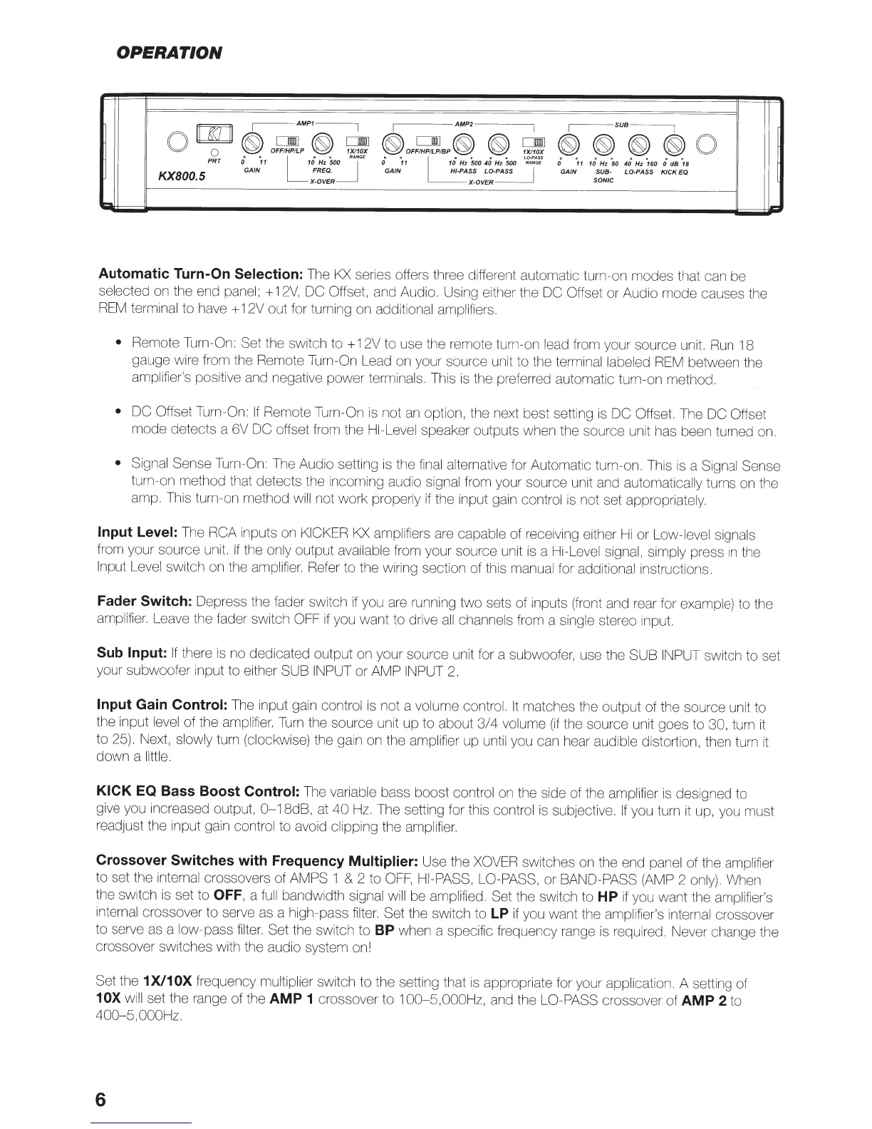
Crossover Switches with Frequency Multiplier:
Use the
XOVER
switches
on
the end panel
of the
amplifier
to set the
internal
crossovers of
AMPS
1
&
2 to
OFF,
HI-PASS, LO-PASS,
or BAND-PASS
(AMP 2
only).
When
the switch
is
set to
OFF,
a
full
bandwidth
signal will
be
amplified. Set the switch to
HP
if
you want the
amplifier's
internal
crossover to serve as a high-pass
filter.
Set
the switch to
LP
if
you want the
amplifier's internal
crossover
to serve as a
low-pass
filter.
Set the switch to
BP
when a specific frequency range
is
required. Never change the
crossover switches with the audio system on!
Set
the
1 X/1
OX
frequency
multiplier
switch to the setting that
is
appropriate for your application.
A setting of
10X
will
set the range of the
AMP 1
crossover to 1
00-5,000Hz,
and the
LO-PASS
crossover of
AMP 2
to
400-5,
OOOHz.
6