Product Description
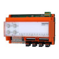
BMA0804
J
Page 10 / 12
2.60-80.804-01-EN | 2019-01-17
NOTE
On delivery, the address “00” is set, which means:
- No bus communication
- No parameterization possible
- Manual operation is effective. The 4 analog outputs can be switched in 10% increments (0..10 V DC)
. In automatic rotary switch position, the output is 0 V DC.
- Sensor inputs in test mode
Commissioning
!
CAUTION
Commissioning by switching on the supply voltage may occur only after the commissioning
technician/engineer has finished configuring the DDC and has set the bus address.
■ Configuration is described in the DDC controller project planning documentation.
■ Before switching on the supply voltage, check the electric installation and the device connections.
■ After configuring the device and switching on the supply voltage, check the functions of the module
and the connected inputs and outputs.
Functional test
It is possible to check the correct wiring and function of the inputs and outputs.
► Set the bus address “00”.
■ The function and wiring of the 4 outputs 0..10 V DC can be tested with the manual/automatic rotary
switch.
■ The correct polarity and wiring of the 8 AI1 through AI8 inputs can be checked with a diode and a
resistor 180 (series connection).
Target display:
- Open contact: Red LED
- Resistance diode combination correctly poled: Green LED
Possible wiring errors:
- Open contact: Green LED
- Resistance diode combination connection: Red LED
 Loading...