BMA0804
Product Description
J
Page 3 / 12
2.60-80.804-01-EN | 2019-01-17
Item
Technical Data
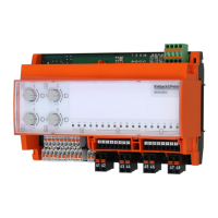
BMA0804 Input/output module with 8 analog inputs and 4 analog outputs
with manual/automatic rotary switch 0..100% for the analog outputs
Nominal voltage 12..24 V DC ± 10%; 2.5 W
Inputs and outputs ■ 4 analog outputs, 0(2)..10 V DC; maximum 2.5 mA
■ 8 analog inputs, See chapter “Sensor Types”, page 4.
■ Separate auxiliary power (terminal 53, 56, 59) 10 V DC; 70 mA
for connecting external setting knobs
■ Support terminal blocks terminal “81” through “88” and terminal “91”
through “98”
max. power load 230 V AC; 6 A (3 A)
Indicators and
Controls
■ 12 LED status indicators of inputs and outputs
■ 6 freely configurable LEDs
■ 1 LED for displaying bus communication
See chapter “LED displays”, page 11.
■ 4 manual/automatic rotary switches for automatic and manual
operation of analog outputs 0..100% 0(2)..10 V DC.
Address switch Two rotary switches for addressing from 01 to 63
Interfaces CAN bus as:
■ Fieldbus, F-bus: 2,000 m; 20 kBd; or
■ Switch cabinet bus, SBM bus: 200 m, 40 kBd (note special CAN BUS
settings. Further information can be found in the DDC4000 project
planning documentation)
Housing Plastic housing
Overvoltage category III
Rated impulse voltage 800 V
Level of contamination 2
Method of operation Type 1
Degree of protection IP20
Ambient temperature 0..55 °C
Ambient humidity 20..80 % r.h.; non-condensing
Mounting TH 35x7.5 top hat rail in closed housing. This device is intended for
installation in a wall-mounted enclosure or switch cabinet with protection
class I or II.
Weight 0.22 kg
Dimensions WxHxD: 143.5 x 90 x 67 mm