BMA0804
Product Description
J
Page 9 / 12
2.60-80.804-01-EN | 2019-01-17
Function and operation
Manual/Automatic Mode
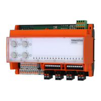
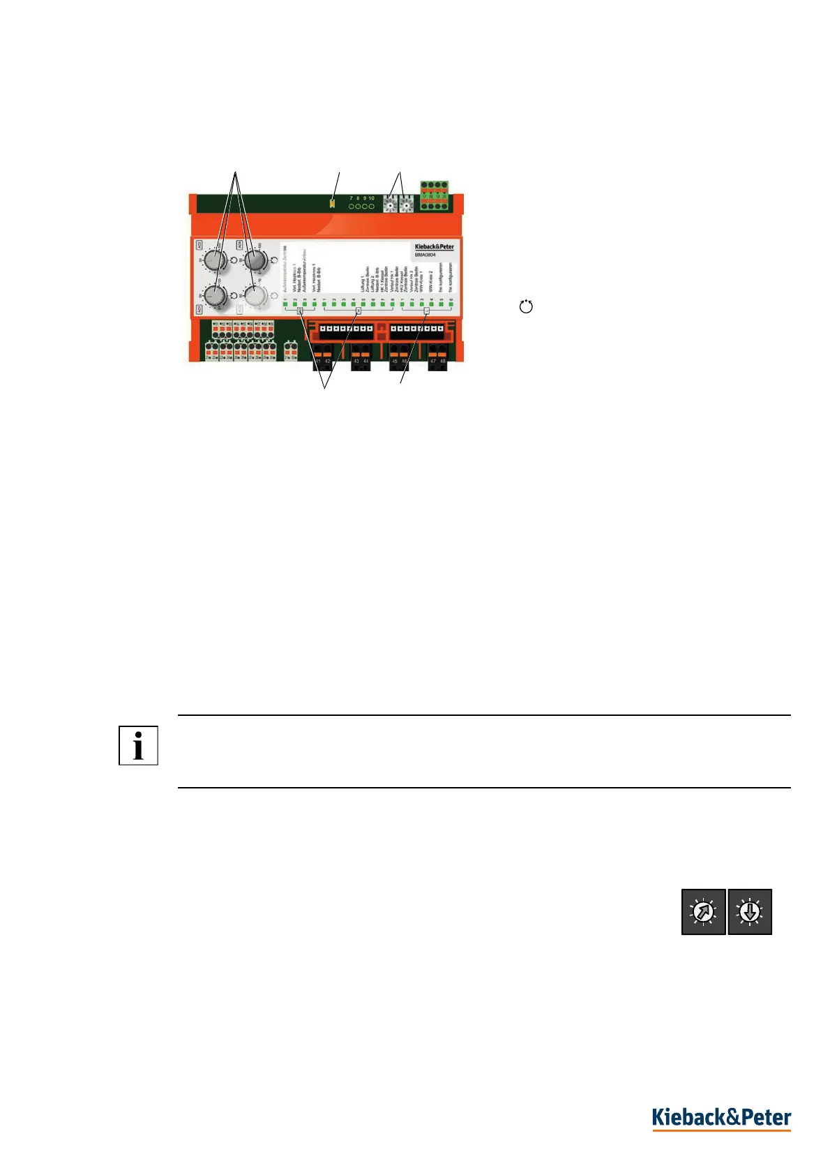
You can switch to the corresponding operating mode using the manual/automatic rotary switch (1).
In manual mode, the respective output signal is set in the range 0 ..100% (0 (2) ..10 V DC) with the
manual/automatic rotary switch (1), depending on the parameterization.
The light intensity of the status LED (5) changes depending on the output signal.
Parameterization
The following functions are defined via parameterization:
- Permanent shutdown of the manual control
- Analog inputs can be configured according to the sensor type table
- Setting range of the analog outputs 2..10V DC or 0..10 V DC.
- Default value for the outputs in the event of bus failure or failure of the automation station
NOTE
Parameterization is retained in the event of a power failure.
Set address 99 to delete the parameterization.
Setting CAN Bus Address
Permitted range for the switch cabinet bus address: 01..63.
Permitted range for fieldbus address: 01..63.
► Set the first number of the bus address on the address switch(3), the second
number on the second rotary address switch (3).
The example shows the address 15.
(1) Manual / automatic rotary switch
= auto, 0 ..50..100 = manual operation
(2) Combi LED (green, red) CAN bus
(3) Address switch
(4) Freely configurable LEDs
(5) Status LEDs of inputs and outputs
1
2
3
4
5
0
1
2
3
4
5
6
7
8
9
0
1
2
3
4
5
6
x 10 x 1
 Loading...