Installation Instructions For Hydraulic Power Units
N01 660 402 / N01 660 408
N01 660 404 / N01 660 410
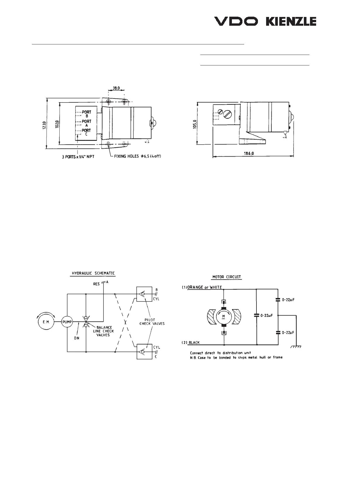
FIGURE 1
The unit shown in figure 1 comprises a small high speed gear pump driven by a permanent
magnetic electric motor. Internal check valves are fitted which, together with the balance
line, ensure that the pump is always primed and ready to run in either direction. The hydrau-
lic output of the pump also flows through pilot check valves which allow free flow and return
whenever the pump is running, but which at other times remain tightly closed and prevent
any leakage through the pump.
FIGURE 2
Installation
The pump should be placed convenient to the hydraulic delivery lines and as near to the ram
cylinder as possible. It should be mounted on a solid base with a minimum of vibration.
Ensure that the helm units are fitted with check valves, otherwise the pump will simply drive
the helm round and not the ram.
Empty the existing oil by releasing a coupling at the lowest point, normally at the ram cylin-
der. Fit “T” pieces in the main delivery lins and couple to the pump by flexible hose (mini-
mum 210 kg/cm
2
test pressure).
8 600 853 Ausgabe 06/96 Seite 5 von 8 (hypump.qxd)