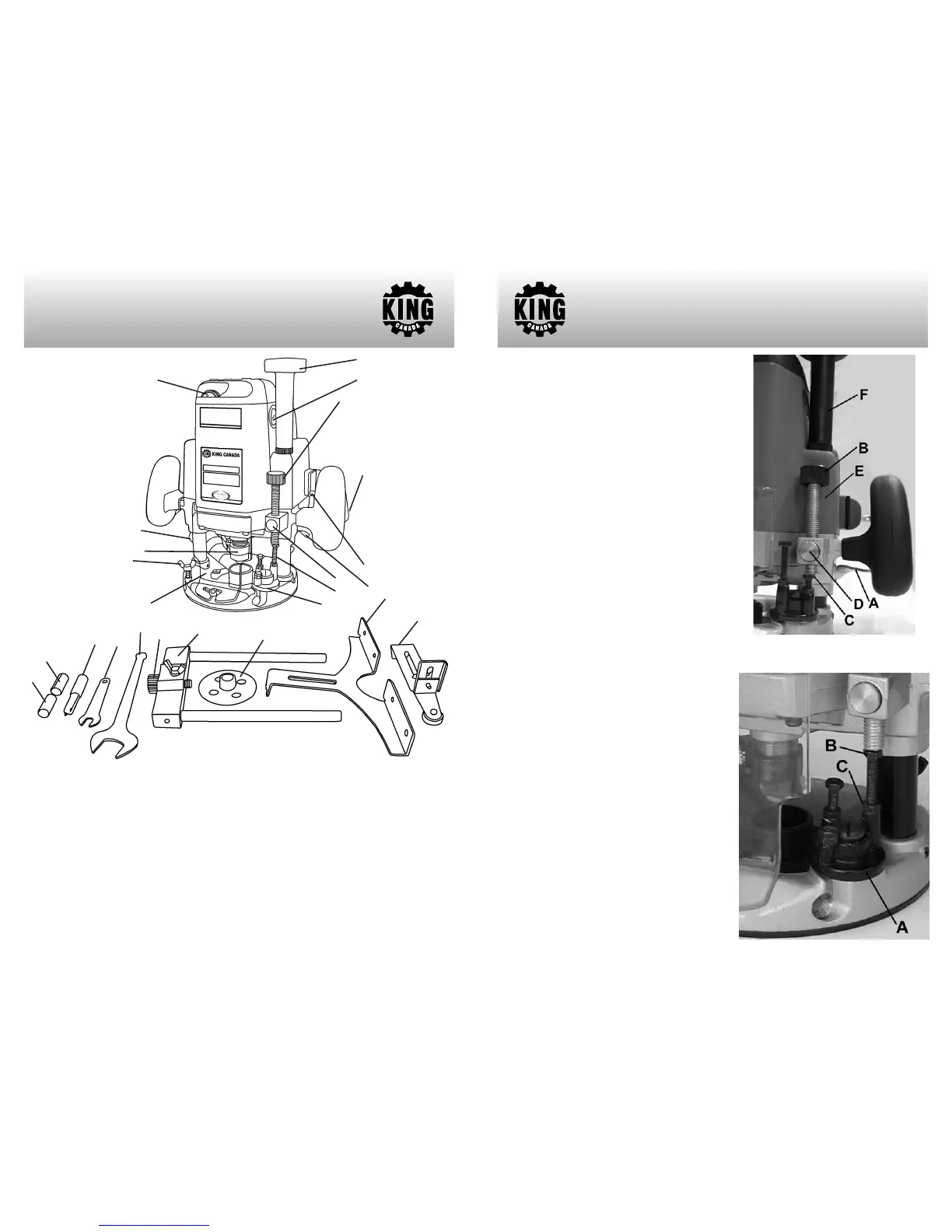
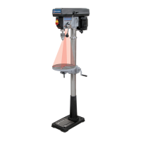
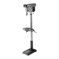
GETTING TO KNOW
YOUR ROUTER
1
4
5
13
12
24
9
10
8
7
6
1- Variable speed selection dial
2- Dust collection port
3- Collet nut
4- Guide support locking wing bolts (1 of 3)
5- Transparent guard
6- Height adjust knob
7- Brush cap (1 of 2)
8- Depth adjust knob
9- Trigger
10- Lock-on button
11- Plunge lock lever
12- Quick release button
13- Depth stop bolts and nuts
14- Depth stop turret
15- 1/4” Collet
16- 3/8” Collet
17- 1/2” Straight router bit
18- 8mm Depth adjustment wrench
19- 24mm Collet nut adjustment wrench
20- Fine adjustment knob
21- Edge guide holder
22-
T
emplate guide
23- Edge guide
24-
T
rim guide
2
3
14
21
23
22
19
18
17
15
16
20
11
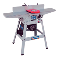
ADJUSTMENTS
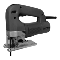
FIGURE 1
Adjusting the Depth of Cut
Place the tool on a flat surface. Lift the lock lever
(A) Fig.1 and lower the tool body until the bit just
touches the flat surface. Press the lock lever
down to lock the tool body. Now lower the depth
adjust knob (B) until it makes contact with the
adjusting hex bolt (C). The depth adjust knob can
be moved rapidly by pressing the quick release
button (D).
To determine the depth of cut, press the quick
release button (D), raise the depth adjust knob
(B) until the desired depth of cut is obtained. The
depth of cut is equal to the distance between the
depth adjust knob and the adjusting hex bolt. The
depth of cut can also be measured using the
depth scale (E) on the tool body.
Now, your router has a preset depth of cut which
can be obtained by lifting the lock lever (A) and
then lowering the tool body until the depth adjust
knob (B) makes contact with the adjusting hex
bolt.
By turning the height adjustment knob (F), the
upper limit of the tool body can be adjusted.
When the tip of the bit is retracted more than
required in relation to the base plate surface, turn
the knob to lower the upper limit.
CAUTION: The depth of cut should not be more
than 13/16” at a pass when cutting grooves.
When you wish to cut grooves more than 13/16”
deep, make several passes with progressively
deeper bit settings.
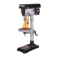
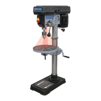
Adjusting Depth Stops
The turret (A) Fig.2 has three adjusting hex. bolts
(B) which raise or lower 1/32” per turn. They allow
you to interchange from three different preset
depths without readjusting the depth adjust knob.
Simply turn the turret to select the desired preset
depth. Adjust the lowest hex bolt to obtain the
deepest depth of cut, adjust the two remaining
hex bolts to obtain shallower depths of cut.
To adjust the hex bolts, first loosen the hex nuts
(C) on the hex bolts with the 8mm wrench and
then turn the hex bolts.
After obtaining the
desired position, tighten the hex nuts while
holding the hex bolts in that position.
FIGURE 2