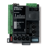
Contents
1. Product description 1
1.1 - Commissioning 1
1.2 - Main features 1
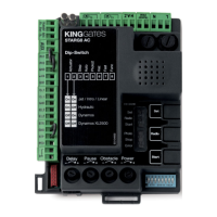
1.3 - Control unit technical features 1
2. Wiring 2
2.1 - STARG8 24 power connection 2
2.2 - STARG8 24 XL power connection 3
2.3 -
STARG8 24 Accessories wiring connection of a typical system
4
2.4 - StarG8 24 Accessories wiring connection 5
3. Control unit settings 6
3.1 - Dip-switch adjustment 6
3.2 - Knob adjustment 7
4. Transmitter (remote control unit) programming 8
4.1 - Start button programming 8
4.2 - Pedestrian (partial) opening button programming 8
4.3 - Deleting all memorised transmitters 9
4.4 - Deleting a single transmitter 9
4.5 - Tools-free transmitter programming 9
5. Programming the gate travel 10
5.1 - Basic programming of the gate travel 10
5.2 - Programming the pedestrian (partial) opening width 11
5.3 - Advanced programming of the gate travel 12
6. Testing and commissioning 13
7. LEDs indication 14
7.1 - Input status indication LEDs 14
7.2 - Error status LED 14
8. RESET procedure 15
9. Devices connectable to the control unit 16
9.1 - Transformer 16
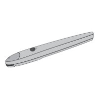
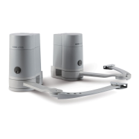
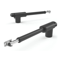
9.2 - Motors 16
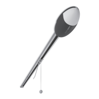
9.3 - Warning light
Note: Professional programming is not required for standard installations. When special functions and adjustments are required, refer
to the advanced / professional programming on the manual instruction (supplied with the unit and available on our website).
16
9.4 - AUX contact 16
9.5 - Safety devices 16
9.6 - 24 VDC accessories’ power supply 18
9.7 - Open gate pilot light 18
9.8 - Limit switches 18
9.9 - Wired commands 18
9.10 - Antenna 18
9.11 - Back-up battery / Energy saving 18
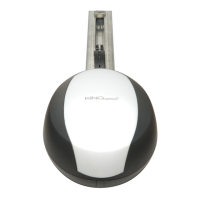
10. MEMO 2000 19
11. F.A.Q. 20
12. Advanced / professional programming - Index 21
 Loading...