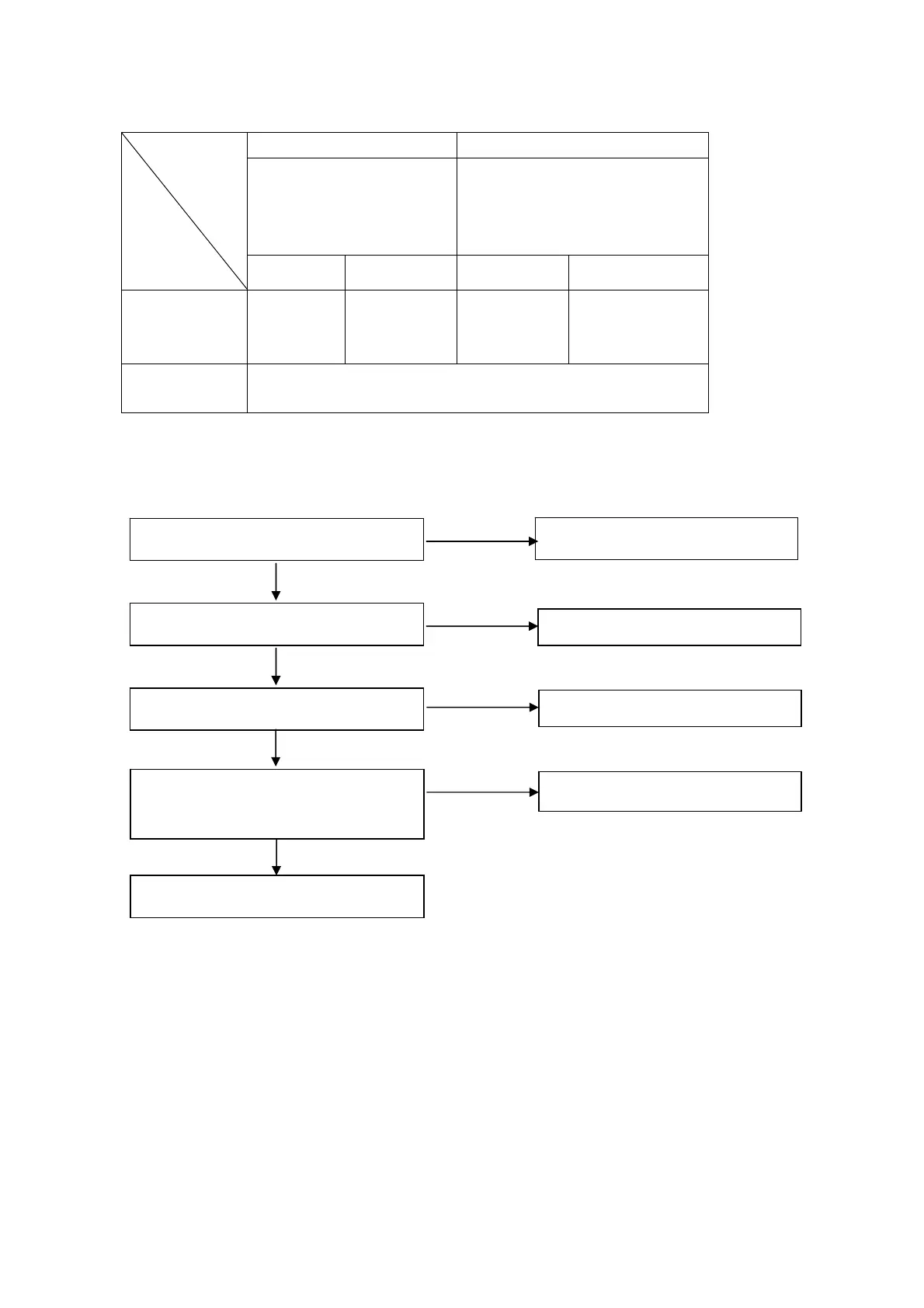
Measure voltage
IG series CG series
Phase wire color:
Black-Black-Black
Sub winding color:
White-White
Phase wire color:
Yellow-Green-Red
Neutral wire color: Black
Sub winding color: Black-Green
Model
Item
120V 230V\240V 120V 230V\240V
Voltage
between
phase wires
>30V >60V >15V >30V
Sub winding
voltage
>1V
i. No AC output (CG series)
Perform the throttle control system
test.
Is the engine speed normal?
Abnormal
Normal
Replace the DC receptacle
Check the DC output
Abnormal
Normal
j. No DC output
k. Parallel no output
■ Make sure that the two PARALLEL I/O are connected correctly by special communication wire.
■ Make sure that the PARALLEL, OUTPUT are inserted into the parallel cable and connected correctly.
■ If there is any disconnection, when you start the parallel generators, some one will be no output and
Check the DC output
Replace the rectifier.
Abnormal
Normal
Measure the resistance between the
blue terminals of the rectifier.
Resistance: 0.12~0.15Ω
Check the wire harness, or replace
the stator.
Abnormal
Normal
Rotor losses magnetism and replace the
rotor.
17